Detailed Description
2.12 Block descriptions
PLC Basic Program Solution Line (P3 sl)
2-102 Function Manual, 08/2005 Edition, 6FC5397-0BP10-0BA0
SD1 : ANY ;
SD2 : ANY ;
SD3 : ANY ;
SD4 : ANY ;
SD5 : ANY ;
SD6 : ANY ;
SD7 : ANY ;
SD8 : ANY ;
END_VAR
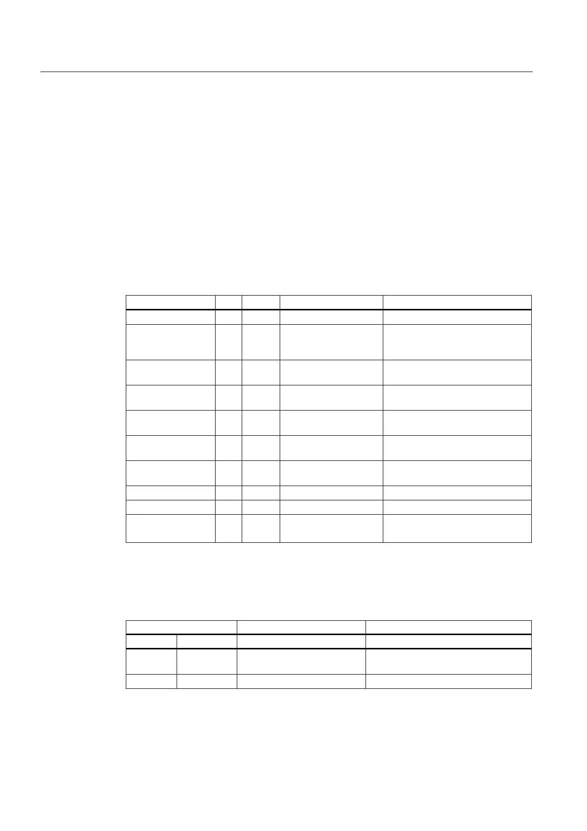
Description of formal parameters
The table below lists all formal parameters of the PUT function.
Signal Type Type Value range Remarks
Req I Bool Job start with positive signal edge
NumVar I Int 1 to 8
(corresponds to use of
Addr1 to Addr8)
Number of variables to be written
Addr1 to Addr8 I Any [DBName].[VarName] Variable identifiers from NC Var
selector
Unit 1 to Unit 8 I Byte Area address, optional for variable
addressing
Column 1 to
Column 8
I Word Column address, optional for
variable addressing
Line 1 to Line 8 I Word Line address, optional for variable
addressing
Error Q Bool Negative acknowledgment of job or
execution of job impossible
Done Q Bool Job successfully executed
State Q Word See error identifiers
SD1 to
SD8
I/O Any P#Mm.n BYTE x...
P#DBnr.dbxm.n BYTE x
Data to be written
Error identifiers
If it was not possible to execute a job, the failure is indicated by "logic 1" on status parameter
error. The error cause is coded at the block output State:
State Meaning Note
WORD H WORD L
1 to 8 1 Access error In high byte number of Var in which
error occurred
0 2 Error in job Incorrect compilation of Var in a job
 Loading...


