Detailed Description
2.12 Block descriptions
PLC Basic Program Solution Line (P3 sl)
Function Manual, 08/2005 Edition, 6FC5397-0BP10-0BA0
2-189
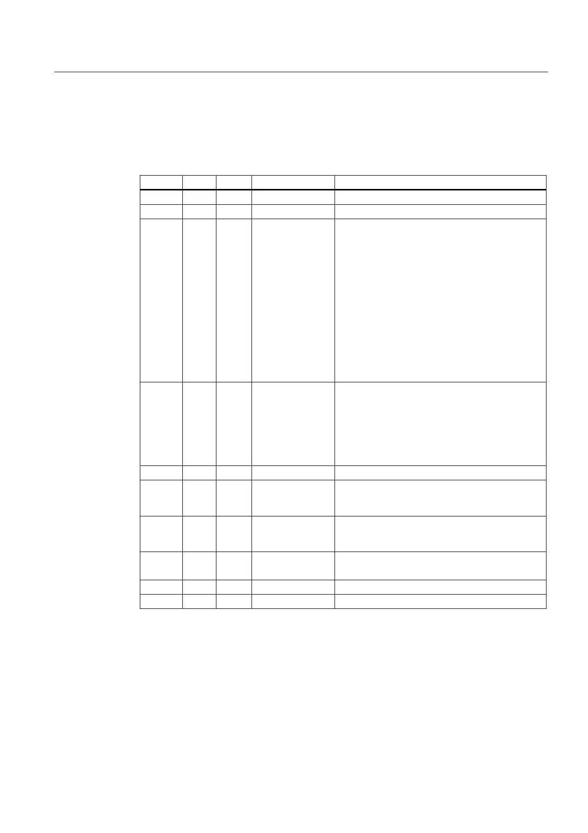
Description of formal parameters
The table below lists all formal parameters of the SpinCtrl function.
Signal Type Type Value range Remarks
Start I Bool Start spindle control from PLC
Stop I Bool Stop spindle control from PLC
Funct I Byte 1 to B#16#0B 1: Position spindle
2: Rotate spindle
3: Oscillate spindle
4: Indexing axis
5: PosAxis metric
6: PosAxis inch
7: PosAxis metric with handwheel override
8: PosAxis inch with handwheel override
9: Rotate spindle with gear stage selection
A: Rotate spindle with constant cutting rate (m/min)
B: Rotate spindle with constant cutting rate
(feet/min)
Mode I Byte 0 to 5 0: Pos to absolute pos
1: Pos incrementally
2: Pos shortest path
3: Pos absolute, positive approach direction
4: Pos absolute, negative approach direction
5: Rotational direction as for M4
AxisNo I Int 1 - 31 No. of axis/spindle to be traversed
Pos I Real ∓ 0,1469368 I -38
to
∓ 0,1701412 I +39
Rotary axis: Degrees
Indexing axis: Indexing position
Linear axis: mm or inches
FRate I Real ∓ 0,1469368 I -38
to
∓ 0,1701412 I +39
Rotary axis and spindle: rev/min
See under table containing info about FRate
InPos Q Bool 1 = Position reached,
or function executed
Error Q Bool 1 = error
State Q Byte 0 to 255 Error code
FRate
The feed rate in FC 18 can also be specified as:
1. Cutting rate with unit m/min or feet/min
2. Constant grinding wheel surface speed in m/s or feet/s
 Loading...


