Detailed Description
2.4 Referencing with incremental measurement systems
Reference Point Approach (R1)
Function Manual, 08/2005 Edition, 6FC5397-0BP10-0BA0
2-13
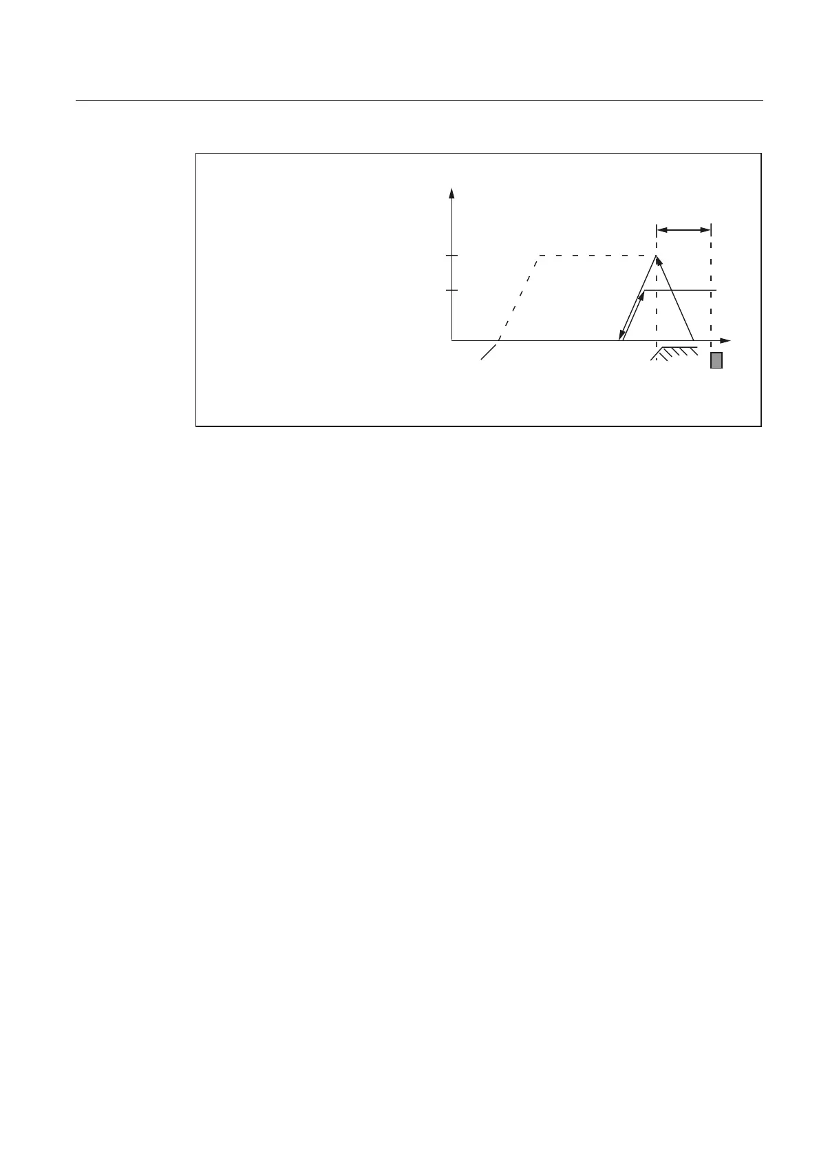
UHIHUHQFHSRLQWDSSURDFKYHORFLW\
6WDUWLQJSRVLWLRQ
RID[LV
'HFHOHUDWLRQ
RIUHIHUHQFHSRLQW
DSSURDFK
9HORFLW\
UHIHUHQFHSRLQWFUHHSYHORFLW\
=HUR
PDUN
PD[LPXPGLVWDQFHWRUHIHUHQFHFDP
'LVWDQFH
0'0$B5()3B9(/2B6($5&+B0$5.(5
0'0$B5()3B9(/2B6($5&+B&$0
0'0$B5()3B0$;B0$5.(5B',67
Fig. 2-6 Synchronization with rising reference cam signal edge
Electronic reference cam offset
Electronic reference cam offset is used for compensating reference cam length increases
caused by temperature:
MD34092 $MA_ REFP_CAM_SHIFT (electronic reference cam offset for incremental
measuring systems with equidistant zero marks)
After a rising or falling reference cam edge is detected the axis is synchronized for the next
encoder zero mark only after the cyclically calculated offset path has been covered. Because
the offset path s
shift
is calculated by the NC in IPO cycles, the following minimum and
maximum offset paths s
shift_min
and s
shift_max
will result:
s
shift_min
= MD34092 $MA_ REFP_CAM_SHIFT
s
shift_max
= MD34092 $MA_ REFP_CAM_SHIFT +
MD34040 $MA_REFP_VELO_SEARCH_MARKER * interpolation cycle
The reference cam offset acts in the direction of zero mark search.
Prerequisite
The reference cam offset is only active for machine axes for which a reference cam has
been parameterized:
MD34000 $MA_REFP_CAM_IS_ACTIVE = 1
 Loading...


