Detailed Description
2.5 Referencing with distance-coded reference marks
Reference Point Approach (R1)
2-22 Function Manual, 08/2005 Edition, 6FC5397-0BP10-0BA0
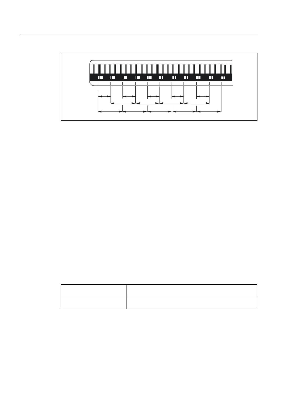
5HIHUHQFHPDUN
Fig. 2-11 DIADUR graduated glass scale with distance-coded reference marks
(dimensions in mm for 20 mm scale division)
Rotary measuring system
For rotary measuring systems, the same applies as for linear measuring systems (see
above).
Determining the absolute offset
In order to determine the absolute offset between machine zero and the position of the 1st
reference mark of a machine axis, the following procedure is recommended:
1. The value zero must be entered for the absolute offset:
MD34090 $MA_REFP_MOVE_DIST_CORR = 0
2. Perform reference point approach.
Note: Reference point approach should be performed at a point in the machine where the
exact position of the machine axis relative to machine zero can be determined easily with
a laser interferometer, for example.
3. Determine the actual position of the machine axis via the HMI user interface.
4. Measure the current position of the machine axis with reference to machine zero.
5. Calculation of absolute offset.
The absolute offset is calculated with respect to the machine coordinate system and
depending on the orientation of the measuring system (equidirectional or inverse) as:
Equidirectional orientation: Absolute offset =
Measured position + indicated actual position
Inverse orientation: Absolute offset =
Measured position - indicated actual position
 Loading...


