Detailed Description
2.3 Configurable gear adaptation
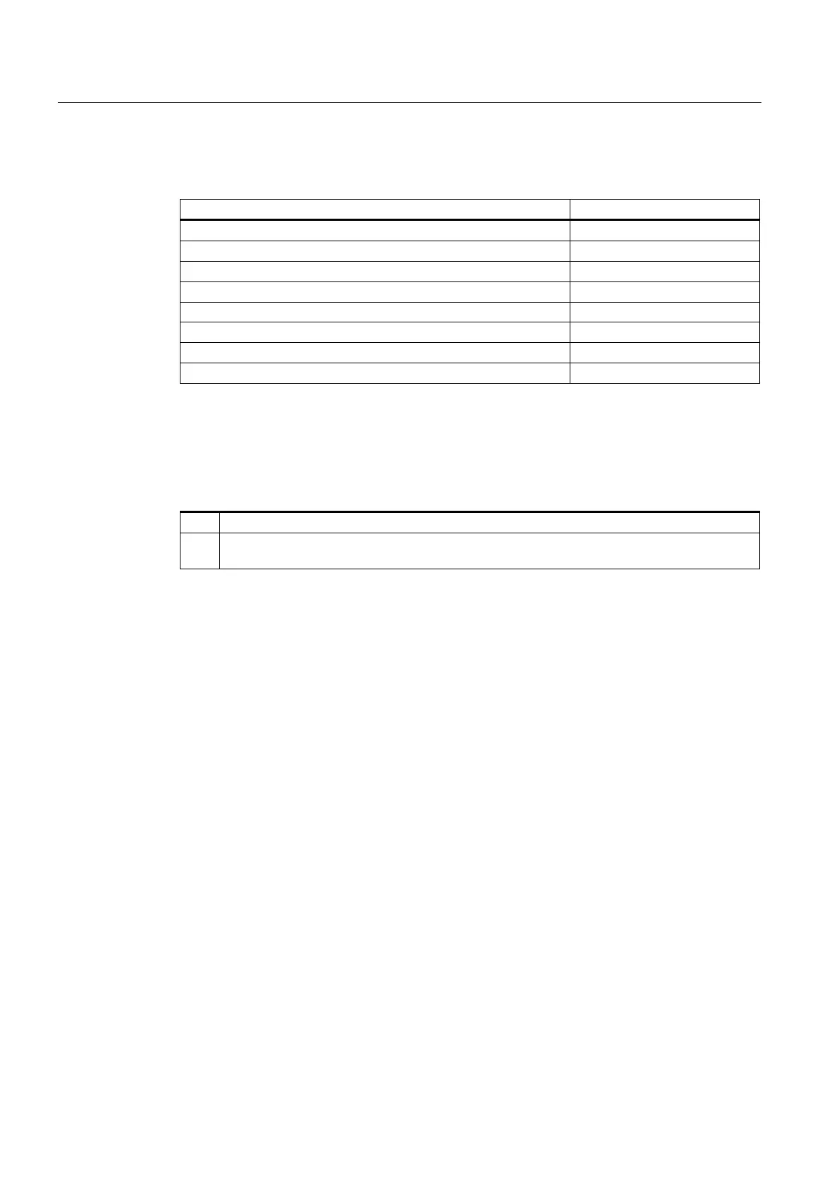
Spindles (S1)
2-34 Function Manual, 08/2005 Edition, 6FC5397-0BP10-0BA0
The parameter sets of gear steps 1 to 5 can be configured with the following machine data:
Min./max. speed
MD35110 $MA_GEAR_STEP_MAX_VELO[n] Max. gear step change
MD35120 $MA_GEAR_STEP_MIN_VELO[n] Min. gear step change
MD35130 $MA_GEAR_STEP_MAX_VELO_LIMIT[n] Max. gear step
MD35140 $MA_GEAR_STEP_MIN_VELO_LIMIT[n] Min. gear step
Acceleration in:
MD35200 $MA_GEAR_STEP_SPEEDCTRL_ACCEL[n] Speed control mode:
MD35210 $MA_GEAR_STEP_POSCTRL_ACCEL[n] Position controller mode
MD35012 $MA_GEAR_STEP_CHANGE_POSITION[n] Gear step change position
Changing parameter sets and formatting
The gear step change also switches over the servo parameter set,
if machine data:
MD35590 $MA_PARAMSET_CHANGE_ENABLE = 0 or 1.
0: The parameter sets cannot be controlled.
1: The servo parameter set is defined primarily by the internal NC switchover at the VDI
interface.
If the parameter sets cannot be controlled:
• For axes, the 1st parameter set with the index 0 is always the one that is applicable.
• For spindles, the 2nd to the 6th parameter set plus one is always active depending on the
gear step selected.
On stipulation of the servo parameter set by the VDI interface, parameter sets 1 to 6 can be
activated via indices 0 to 5.
The following applies:
• For the axes involved, the parameter set number that corresponds to the master spindle
gear step incremented by one is active. This then corresponds to parameter set numbers
2 to 6.
• For spindles, the 2nd to the 6th parameter set plus one is always active depending on the
gear step selected.
If:
MD35590 $MA_PARAMSET_CHANGE_ENABLE = 2,
the servo parameter set is specified by the PLC.
A gear step can be specified by the PLC at any time.
Sequence for switchover
If the new gear step is preselected, the following sequence is implemented:
 Loading...


