Detailed Description
2.3 Tool cutting edge
Tool Compensation (W1)
2-32 Function Manual, 08/2005 Edition, 6FC5397-0BP10-0BA0
Note
All three tool parameters 3 to 5 (tool length 1 to 3) are always calculated in the three
geometry axes, irrespective of the tool type.
If more tool lengths than the minimum required are entered in tool parameters 3 to 5 for one
tool type (only tool length 1 is required for tool type 2xx), these additional tool lengths are
calculated in the geometry axes without an alarm.
Note
Please refer to the following documentation for information about entering tool dimensions
(lengths) in tool parameters 3 to 4 (tool lengths 1 to 3) and how these are calculated in the
three geometry axes:
References:
/BA/ Operator's Guide.
)
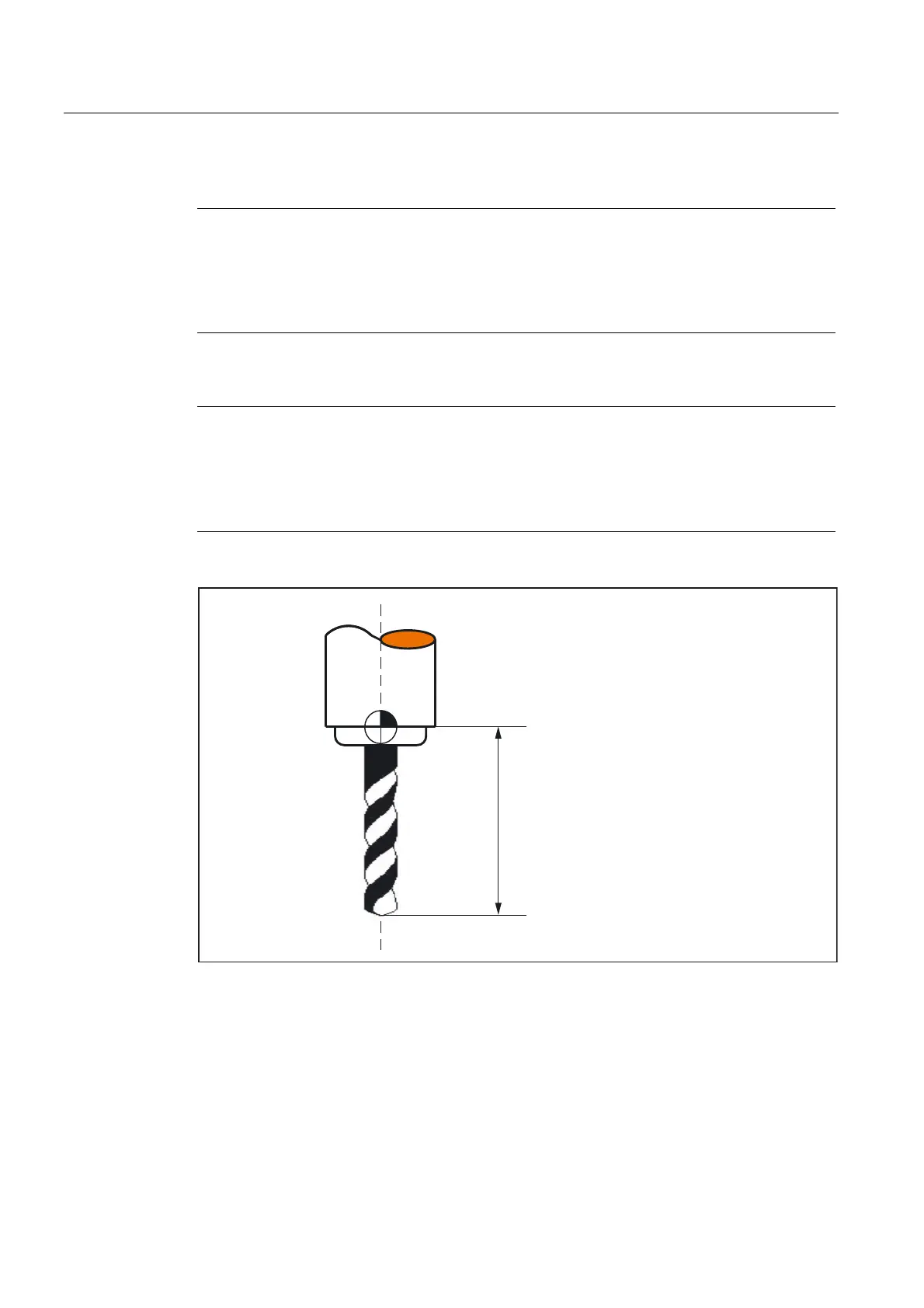
/HQJWKWRROSDUDPHWHU
) WRROKROGHUUHIHUHQFHSRLQW
Fig. 2-8 Twist drill (tool type 200) with tool length (tool parameter 3)
Special feature
The active size of the tool is only defined when the geometry tool length compensation (tool
parameters 3 to 5) and the wear tool length compensation (tool parameters 12 to 14) are
added together. The base-dimension/adapter-dimension tool length compensation is also
added in order to calculate the total tool length compensation in the geometry axes.
 Loading...


