Detailed Description
2.4 Tool: Tool radius compensation 2D (TRC)
Tool Compensation (W1)
Function Manual, 08/2005 Edition, 6FC5397-0BP10-0BA0
2-49
• Modal G code (G340, G341), which defines the subdivision of the movement into
individual blocks from the start point to the end point
6WUDLJKWOLQH
RUFLUFOH
,QIHHGPRYHPHQW
6WUDLJKWOLQH
FLUFOHRUKHOL[
0DFKLQLQJSODQH
*
*
3 33 3
',6&/ ',6&/
33 3
3 33
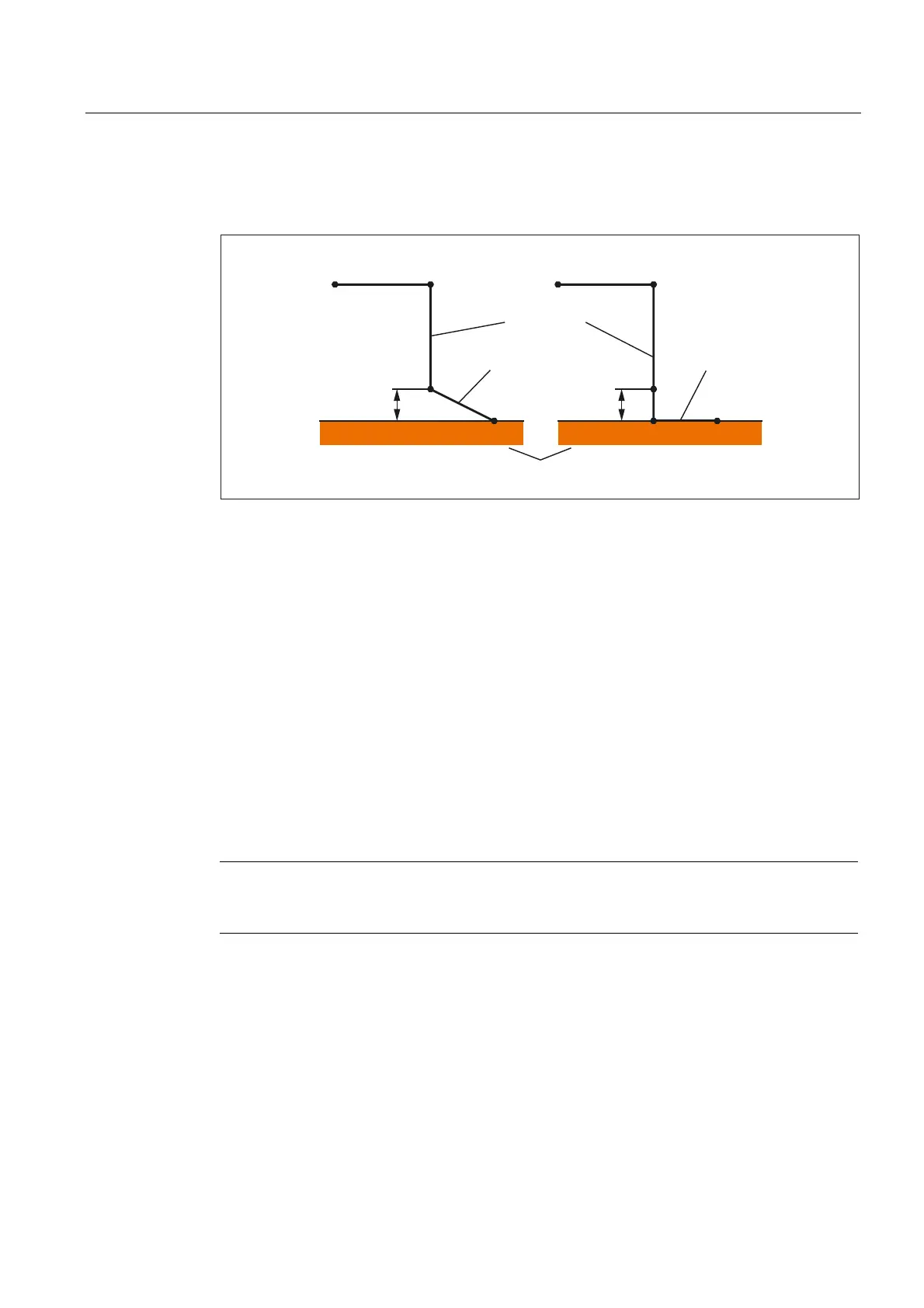
Fig. 2-20 Sequence of the approach movement depending on G340/G341
G340: The approach characteristic from P
0
to P
4
is shown in the figure.
If G247 or G347 is active (quadrant or semicircle) and start point P
3
is outside the machining
plane defined by the end point P
4
, a helix is inserted instead of a circle. Point P
2
is not
defined or coincides with P
3
.
The circle plane or the helix axis is determined by the plane, which is active in the SAR
block (G17 - G19), i.e., the projection of the start tangent is used by the following block,
instead of the tangent itself, to define the circle.
The movement from point P
0
to point P
3
takes place along two straight lines at the velocity
valid before the SAR block.
G341: The approach characteristic from P
0
to P
4
is shown in the figure.
P
3
and P
4
are located within the machining plane, with the result that a circle is always
inserted instead of a helix with G247 or G347.
Note
Active, rotating frames are included in all cases where the position of the active plane G17 -
G19 (circle plane, helix axis, infeed movements perpendicular to the active plane) is relevant.
 Loading...


