Detailed Description
2.11 Jerk limitation with path interpolation (SOFT) (channel-specific)
Acceleration (B2)
2-20 Function Manual, 08/2005 Edition, 6FC5397-0BP10-0BA0
Disadvantages
Longer machining times compared with stepped acceleration profile when the same
maximum velocity and acceleration values are used.
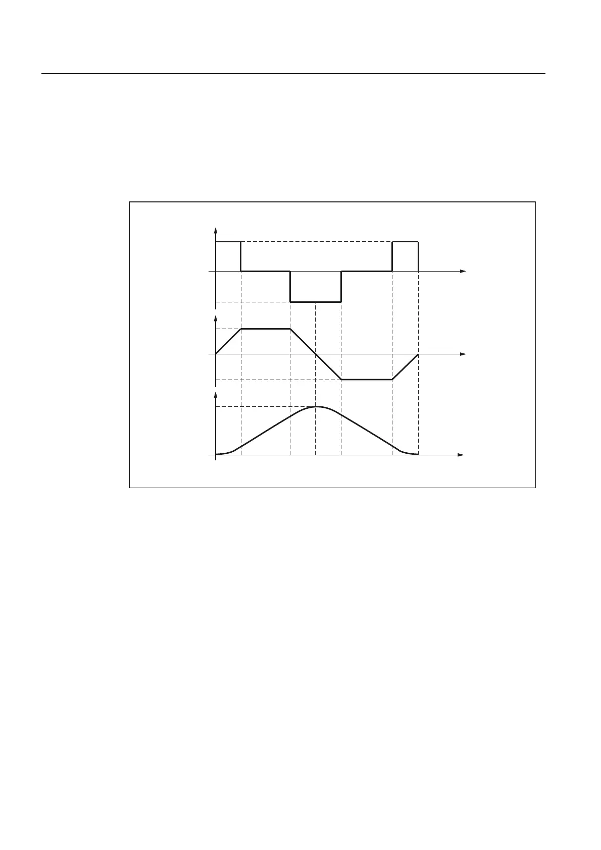
Acceleration profile
W
U
PD[
U
U
PD[
W
WW W WWW
D
PD[
D
D
PD[
Y
PD[
W
W
Y
Fig. 2-4 Jerk, acceleration and velocity schematic with jerk limitation acceleration profile
r
max
: Maximum jerk value
a
max
: Maximum acceleration value
v
max
: Maximum velocity value
t: Time
The following features of the acceleration profile can be identified from the figure above:
• Interval: t
0
- t
1
Constant jerk with +r
max
; linear increase in acceleration; quadratic increase in velocity
• Interval: t
1
- t
2
Constant acceleration with +a
max
; linear increase in velocity
• Interval: t
2
- t
3
Constant jerk with -r
max
; linear decrease in acceleration; quadratic decrease in excessive
velocity until maximum value +v
max
is reached
 Loading...


