Detailed Description
2.1 NC/PLC interface signals
Various NC/PLC Interface Signals and Functions (A2)
Function Manual, 08/2005 Edition, 6FC5397-0BP10-0BA0
2-13
3RVLWLRQUHIHUHQFHYDOXH
IURP
,QWHUSRODWRU
3RVLWLRQ
6SHHG
FRQWUROOHU
3RZHU
0RWRU
(QFRG
(QFRG
B
DFW
DFW
6HW
30
30
30
30
3DUNLQJD[LV
B
FRQWUROOHU
FRQWUROOHU
L
Q
L
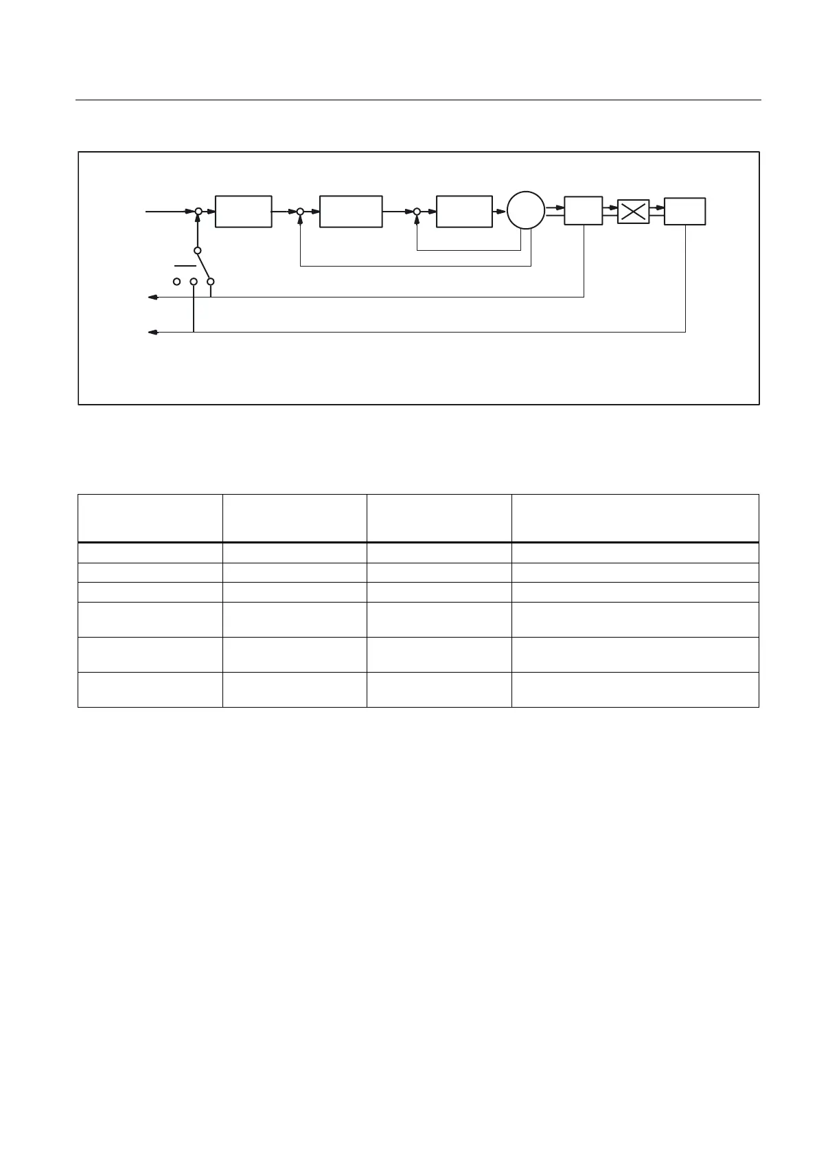
Fig. 2-4 Position measuring system 1 and 2
The table below shows the functionality of the interface signals in conjunction with the "servo
enable".
(DB31, ... DBX1.5)
Position measuring
system 1
(DB31, ... DBX1.6)
Position measuring
system 2
(DB31, ... DBX2.1)
Servo enable
Function
1 0 (or 1) 1 Position measuring system 1 active
0 1 1 Position measuring system 2 active
0 0 0 "Parking" active
0 0 1 Spindle without position measuring system
(speed-controlled)
1 -> 0 0 -> 1 1 Switchover: Position measuring system
1 -> 2
0 -> 1 1 -> 0 1 Switchover: Position measuring system
2 -> 1
DB31, ... DBX2.1 (servo enable)
Setting the servo enable closes the machine axis position control loop. The machine axis is
in closed-loop position control.
DB31, ... DBX2.1 = 1
Canceling the servo enable opens the machine axis position control loop and, subject to a
delay, speed control loop:
DB31, ... DBX2.1 = 0.
Activation modes
The closed-loop servo enable for a machine axis is influenced by:
• PLC user program by means of the following NC/PLC interface signals:
– DB31, ... DBX2.1 = 0 (servo enable)
– DB31, ... DBX21.7 = 0 (pulse enable)
– DB31, ... DBX93.5 = 0 (Drive Ready)
– DB10, DBX56.1 = 1 (EMERGENCY STOP)
 Loading...


