Detailed Description
2.3 Axis/spindle service display
Diagnostic Tools (D1)
2-12 Function Manual, 08/2005 Edition, 6FC5397-0BP10-0BA0
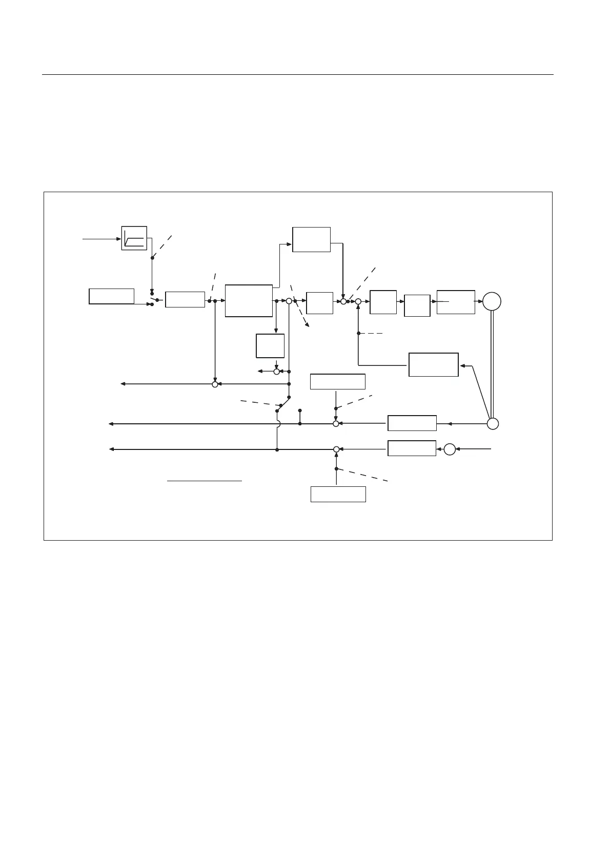
Control technology concept
The figure below shows at which points in the controlloop the axis and spindle information is
read off.
0
3RVLWLRQ
FRQWURO
OHU
Spindle speed setpoint
current
Error signal
Position setpoint
(speed setpoint)
Spindle
speed
setpoint
prog.
Abs. compensation value
Measuring system 2
Speed setpoint [%]
*
*
Actual speed value [%]
Control
parameter set
Contour
deviation
Following error
e.g. from
direct
measuring
system
Abs. compensation value
Measuring system 1
Actual position value of measuring system 2
Actual position value of measuring system 1
Active
measuring
system
6HUYRJDLQIDFWRUFDOFXODWHG
6SHHGVHWSRLQW
)ROORZLQJHUURU
9DOXHLVGLVSOD\HGLQXVHULQWHUIDFH
,WDOLFIRQW
)LQH
LQWHUSRODWRU
-HUNOLPLWDWLRQ
'\QDPLF
UHVSRQVH
DGDSWDWLRQ
)HHG
IRUZDUG
FRQWURO
&RQWURO
ORRS
PRGHO
6SHHG
FRQW
UROOHU
&XUUHQW
FRQWURO
OHU
3RZHU
VHFWLRQ
$FWXDOVSHHG
YDOXH
VSHFLILFDWLRQ
&RPSHQVDWLRQ
%DFNODVK/(&
$FWXDOYDOXH
SURFHVVLQJ
$FWXDOYDOXH
SURFHVVLQJ
&RPSHQVDWLRQ
%DFNODVK/(&
,QWHUSRODWRU
,32
식
Fig. 2-2 Overview diagram of axis and spindle information
Checks
Check of the position controller setting
A simple check of the position controller setting can be made by means of the service axis
screen.
To this end, the number 1 (corresponding to KV = 1) is entered in machine datum:
MD32200 $MA_POSCTRL_GAIN [n] (KV factor).
The change takes effect immediately.
 Loading...


