Detailed Description
2.9 Identifying defective drive modules
Diagnostic Tools (D1)
Function Manual, 08/2005 Edition, 6FC5397-0BP10-0BA0
2-33
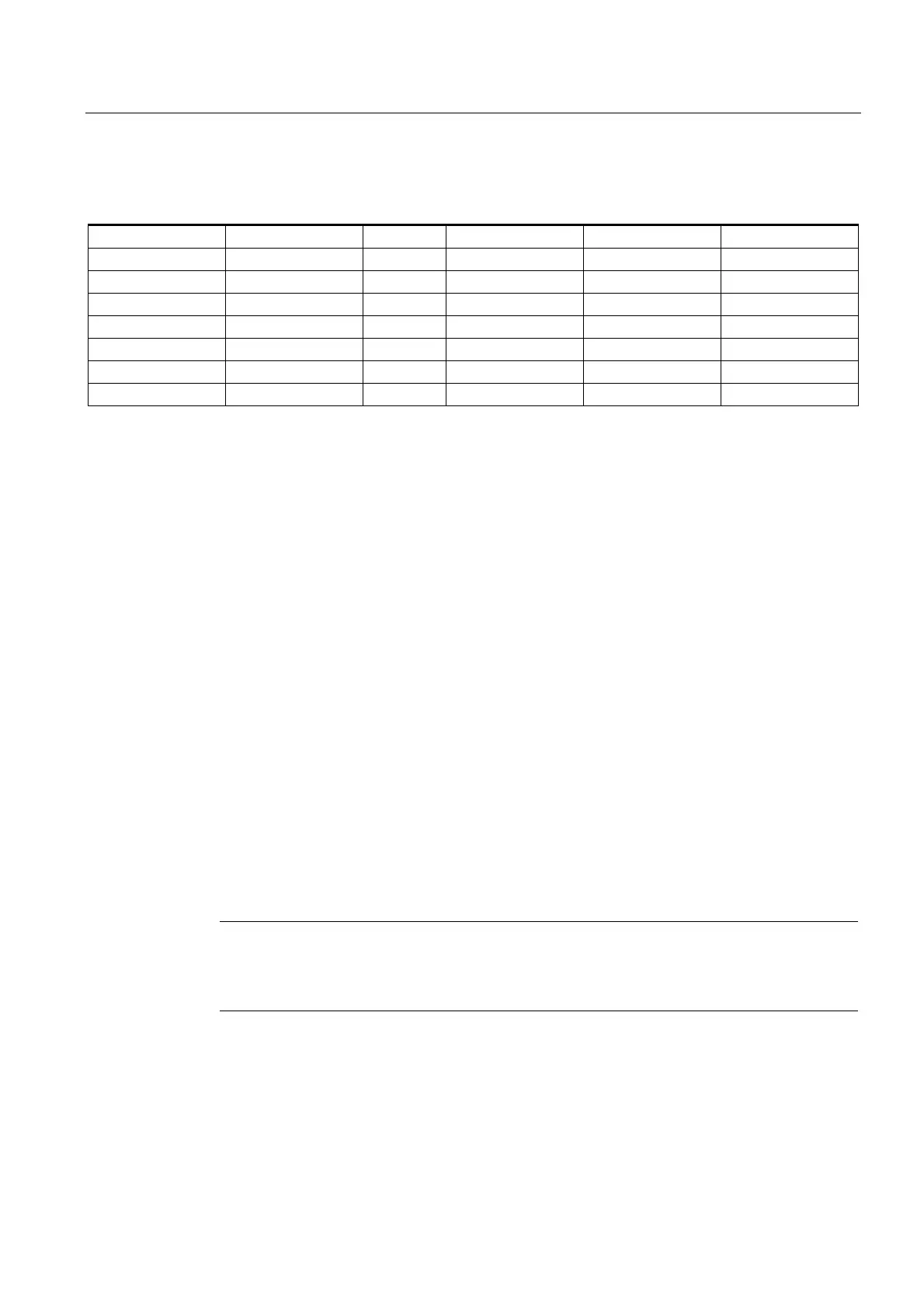
Table 2-5 Bus configuration example
Module Drive no. Active Type Module type Power section code
1 10 1 ARM/MSD Axis 6
Left 1 1 SRM/FDD Axis 14
Right 2 1 SRM/FDD Axis 14
Left 4 1 HLA Axis
Right 5 1 ANA Axis
4 12 1 SLM Axis 11
5 11 1 PER DMPC
Module "2" must now be removed:
• Machine datum:
MD13030 $MN_DRIVE_MODULE_TYPE
is to be selected on the "General MD" MD screen.
• DRIVE_MODULE_TYPE[0] = 1
DRIVE_MODULE_TYPE[1] = 2 <- set this entry to zero
DRIVE_MODULE_TYPE[2] = 2 <- set this entry to zero
DRIVE_MODULE_TYPE[3] = 2
DRIVE_MODULE_TYPE[4] = 2
DRIVE_MODULE_TYPE[5] = 1
DRIVE_MODULE_TYPE[6] = 9
• After the changes, the table looks like this:
DRIVE_MODULE_TYPE[0] = 1
DRIVE_MODULE_TYPE[1] = 0
DRIVE_MODULE_TYPE[2] = 0
DRIVE_MODULE_TYPE[3] = 2
DRIVE_MODULE_TYPE[4] = 2
DRIVE_MODULE_TYPE[5] = 1
DRIVE_MODULE_TYPE[6] = 9
• Alarms 300020 "Drive 1 removed for diagnostics" and 300020 "Drive 2 removed for
diagnostics" are displayed.
Internally simulated drives are used for all axes which had settings on the removed drive
numbers. If the controller is engaged for the drives that are still installed, these drives
operate in the normal way. Interpolative traversal of all axes is disabled.
Note
If alarm 300003 "Axis xx drive yy incorrect module type zz" appears, then you have removed
only one part of a 2axis module. In this case, you should check the module type in the drive
configuration display. For removed modules, "NO" axis type is shown.
 Loading...


