Detailed Description
2.2 Metric/inch measuring system
Velocities, Setpoint/Actual-Value Systems, Closed-Loop Control (G2)
Function Manual, 08/2005 Edition, 6FC5397-0BP10-0BA0
2-15
Example 2:
The definition is made here by programming G71 in the synchronized action.
N100 R1=0
N110 G0 X0 Z0
N120 WAITP(X)
N130 ID=1 WHENEVER $R1==1 DO G71 POS[X]=10
N140 R1=1
N150 G71 Z10 F10 ;Z=10 mm X=10 mm
N160 G70 Z10 F10 ;Z=254 mm X=10 mm (X posit. always at 0 mm)
N170 G71 Z10 F10 ;Z=10 mm X=10 mm
N180 M30
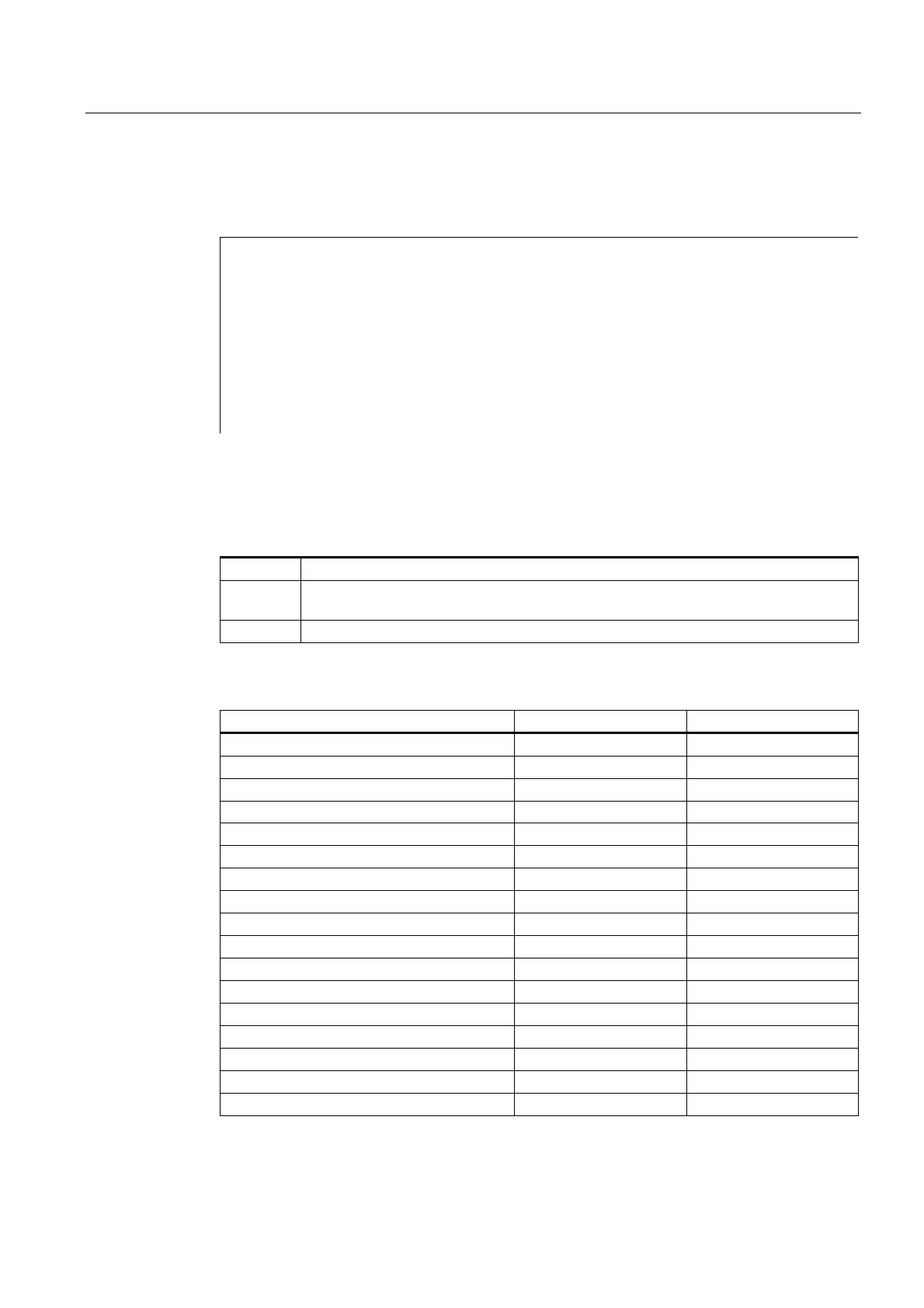
Comparison: G70/G71-G700/G710
Where:
P: Data is read/written in the programmed measuring system
G: Data is read/written in the basic system
(MD10240 $MN_SCALING_SYSTEM_IS_METRIC).
R/W: Read/Write
Comparison:
Range G70/G71 G700/G710
Parts program Parts program
R/W R/W
Display, decimal places (WCS) P/P P/P
Display, decimal places (MCS) G/G G/G
Feedrates G/G P/P
Positional data X, Y, Z P/P P/P
Interpolation parameters I, J, K P/P P/P
Circle radius (CR) P/P P/P
Polar radius (RP) P/P P/P
Pitch P/P P/P
Programmable FRAME P/P P/P
Settable FRAMES G/G P/P
Basic frames G/G P/P
Work offsets external G/G P/P
Axial preset offset G/G P/P
Operating range limit (G25/G26) G/G P/P
Protection zones P/P P/P
 Loading...


