Detailed Description
2.1 Axes
Axis Types, Coordinate Systems, Frames (K2)
2-14 Function Manual, 08/2005 Edition, 6FC5397-0BP10-0BA0
0'$;&21)B0$&+$;B1$0(B7$%
0'63,1'B$66,*1B72B0$&+$;
&
:
%
=
<
;
0'$;&21)B&+$1$;B1$0(B7$% 0'$;&21)B0$&+$;B86('
0'$;&21)B*(2$;B$66,*1B7$%0'$;&21)B*(2$;B1$0(B7$%
&
:=0
%
=
<
;
=
<
;
&KDQQHO
&KDQQHO
VWJHRPHWU\D[LV>@
QGJHRPHWU\D[LV>@
UGJHRPHWU\D[LV>@
&KDQQHO
&KDQQHO
VWFKDQQHOD[LV>@
QGFKDQQHOD[LV>@
UGFKDQQHOD[LV>@
WKFKDQQHOD[LV>@
WKFKDQQHOD[LV>@
WKFKDQQHOD[LV>@
WKFKDQQHOD[LV>@
WKFKDQQHOD[LV>@
VWPDFKLQHD[LV>@
QGPDFKLQHD[LV>@
UGPDFKLQHD[LV>@
WKPDFKLQHD[LV>@
WKPDFKLQHD[LV>@
WKPDFKLQHD[LV>@
WKPDFKLQHD[LV>@
WKPDFKLQHD[LV>@
&KDQQHO &KDQQHO
&KDQQHO
&KDQQHO
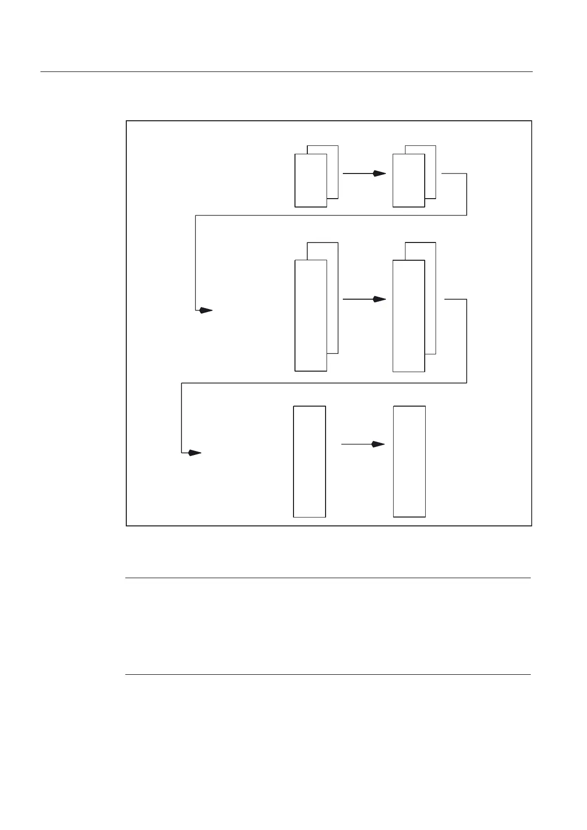
Fig. 2-4 Axis configuration
Note
Leading zeroes in user-defined axis identifiers are ignored.
Example:
MD10000 AXCONF_MACHAX_NAME_TAB[0] = X01 is equivalent to X1
The geometry axes must be assigned to the channel axes in ascending order leaving no
gaps.
 Loading...


