Detailed description
2.6 Interface structure
Power Line Basic PLC Program (P3)
2-32 Function Manual, 08/2005 Edition, 6FC5397-0BP10-0BA0
%\WH
'%
1&.
%3
00&
'HFRGLQJKDQG
ZKHHOVHOHFWLRQ
H[WHUQDORXWSXWV
6HWSRLQWVIRUDQDORJ1&.RXWSXWV
H[WHUQDOLQSXWV
$FWXDOYDOXHVIRUDQDORJ1&.LQSXWV
H[WHUQDORXWSXWV
6HWSRLQWVIRUGLJLWDO1&.RXWSXWV
([WHUQDOLQSXWV
$FWXDOYDOXHVIRUGLJLWDO1&.LQSXWV
([WHUQDORXWSXWV
&RQWURORIDQDORJ1&.RXWSXWV
([WHUQDOLQSXWV
&RQWURORIDQDORJ1&.LQSXWV
([WHUQDORXWSXWV
&RQWURORIGLJLWDO1&.RXWSXWV
([WHUQDOLQSXWV
&RQWURORIGLJLWDO1&.LQSXWV
6RIWZDUHFDP
6WDWXVVLJQDOV
%DVLFSURJUDPVWDWXVVLJQDOV
00&VWDWXVVLJQDOV
+DQGZKHHOVHOHFWLRQ
5HVHUYH
2QERDUGRXWSXWV
6HWSRLQWVIRUGLJLWDO1&.RXWSXWV
2QERDUGLQSXWV
$FWXDOYDOXHVIRUGLJLWDO1&.LQSXWV
.H\VZLWFK(0(5*(1&<6723
5HVHUYH
2QERDUGRXWSXWV
&RQWURORIGLJLWDO1&.RXWSXWV
$[LVLQWHUIDFHJHR
D[LVLQWHUIDFHLQ
FKDQQHO
2QERDUGLQSXWV
&RQWURORIGLJLWDO1&.LQSXWV
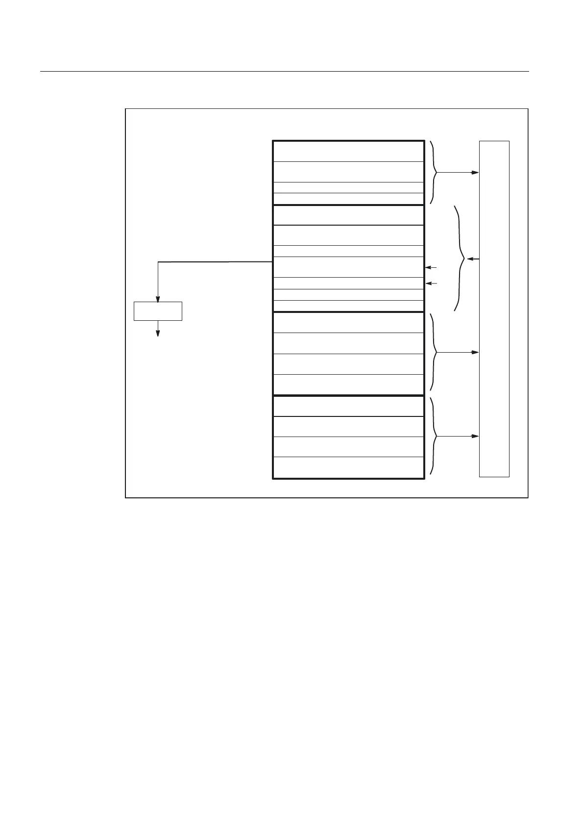
Fig. 2-4 PLC/NC interface
Digital/analog inputs/outputs of the NCK
The following must be noted with respect to the digital and analog inputs and outputs of the
NCK:
Inputs:
• All input signals or input values of the NCK are also transferred to the PLC.
• The transfer of signals to the NC parts program can be suppressed by the PLC. Instead,
a signal or value can be specified by the PLC.
• The PLC can also transfer a signal or value to the NCK even if there is no hardware for
this channel on the NCK side.
 Loading...


