Detailed description
2.6 Interface structure
Power Line Basic PLC Program (P3)
Function Manual, 08/2005 Edition, 6FC5397-0BP10-0BA0
2-41
NEG
$6
&EXV
3EXV
2SV\V
3*
1&8
23
0&3
++8
8VHUNH\VGLVSOD\V
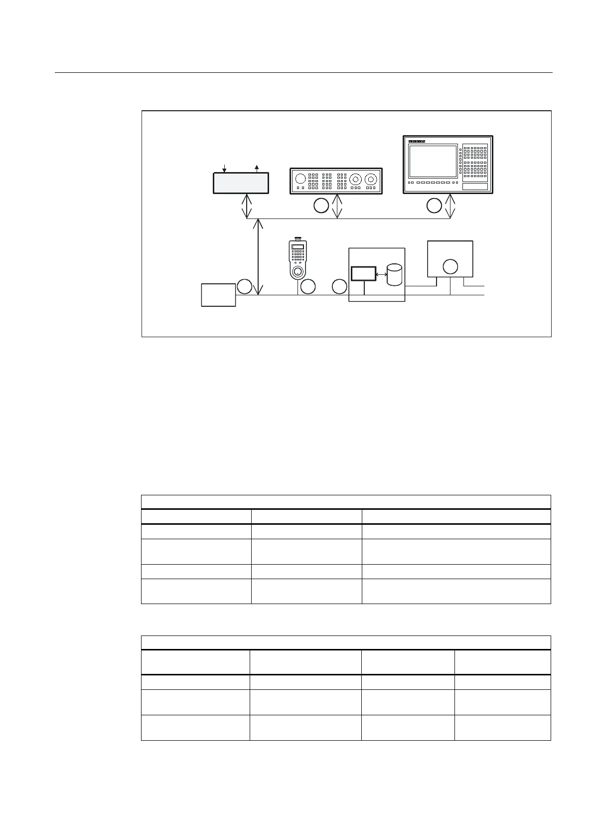
Fig. 2-10 Connection of the machine control panel for 810D
Bus addresses
The default bus addresses for the standard configurations are entered in the "Connecting the
MCP on the 810D" figures. In addition to the bus addresses, the implicit communication
service (global data) also requires the definition of a GD circle number.
The following should be taken into account when allocating bus addresses (node no.):
Bus addresses 840D
The two bus segments on the 840D must be examined separately:
Operator panel bus segment:
Bus station Perm. setting range Standard setting
Operator panel (OP) 1 - 31 1
Machine control
panel/keyboard interface
15 (setting via DIP fix)
COM module 31 13
Programming device/PC
(e.g., for startup)
fixed 0
PLC bus segment:
Bus station Setting range Default
setting
Comment
PLC 31 2
COM module Fixed depending on PLC
address
3
Programming device/PC
(e.g., for startup)
fixed 0
 Loading...


