It is sufficient for the current criterion that current flow is detected in one of the involved phases.
The phase–phase undervoltage protection can also be blocked via a binary input
>27-Vphph BLOCK
. There is
an automatic blocking if the measuring voltage failure was detected or voltage mcb tripping was indicated
(internal blocking of the phases affected by the voltage failure).
Undervoltage Positive Sequence System V
1
The device calculates the positive sequence system according to its defining equation
V
1
=
1
/
3
·(V
A
+ a·V
B
+ a
2
·V
C
)
where a = e
j120°
.
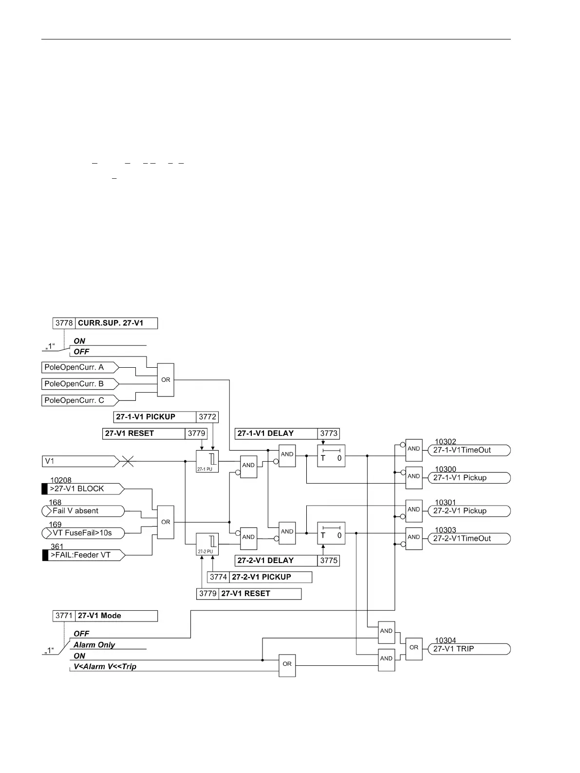
The resulting positive sequence voltage is fed to the two threshold elements 27-1-V1 PICKUP (address
3772) and 27-2-V1 PICKUP (address 3774) (see Figure 2-51). Combined with the associated time delays
27-1-V1 DELAY (address 3773) and 27-2-V1 DELAY (address 3775) these elements form a two-element
overvoltage protection for the positive sequence system.
Current can be used as an additional criterion for the undervoltage protection of the positive sequence system
(current criterion CURR.SUP. 27-V1, address 3778). An undervoltage is only detected if the current flow is
detected in at least one phase together with the undervoltage criterion.
The undervoltage protection for the positive sequence system can be blocked via the binary input
>27-V1
BLOCK
. The stages of the undervoltage protection are automatically blocked if voltage failure is detected
(“Fuse-Failure-Monitor”, also see Section 2.14.1 Measurement Supervision) or, if the trip of the mcb for the
voltage transformer is indicated via the binary input
>FAIL:Feeder VT
(internal blocking).
[lo-unterspg-mitsys-20101108, 1, en_US]
Figure 2-51
Logic diagram of the undervoltage protection for positive sequence voltage system
Functions
2.8 Undervoltage and Overvoltage Protection (optional) 27/59
114 SIPROTEC 4, 7SD80, Manual
E50417-G1100-C474-A2, Edition 02.2018

 Loading...


