[lo-ip-stufe-amz-iec-20101108, 1, en_US]
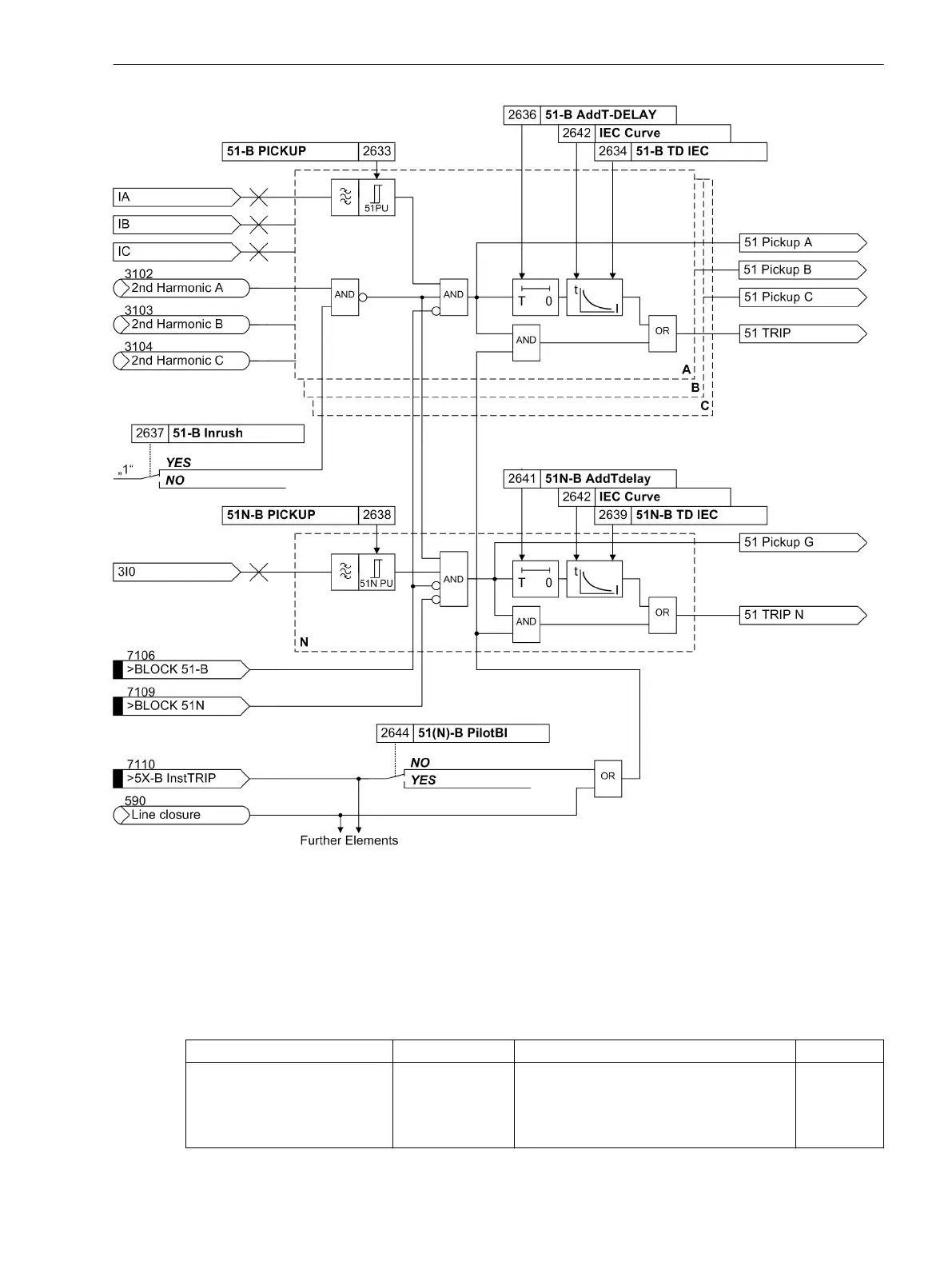
Figure 2-28
Logic diagram of the 51 element (inverse time overcurrent protection) - Example for IEC char-
acteristic
Pickup Logic and Tripping Logic
The pickup signals of the individual phases (or ground) and of the individual elements are interlinked in such a
way that both the phase information and the element which has picked up are indicated (Table 2-1).
Table 2-1
Pickup signals of the single phases
Internal indication Display Output indication No.
50-2 PU A
50-1 PU A
50-3 PU A
51 PU A
Figure 2-26
5X-B Pickup ØA
7162
Functions
2.4 Backup overcurrent
SIPROTEC 4, 7SD80, Manual 75
E50417-G1100-C474-A2, Edition 02.2018

 Loading...


