[sc_IO240 connection clamps, 1, en_US]
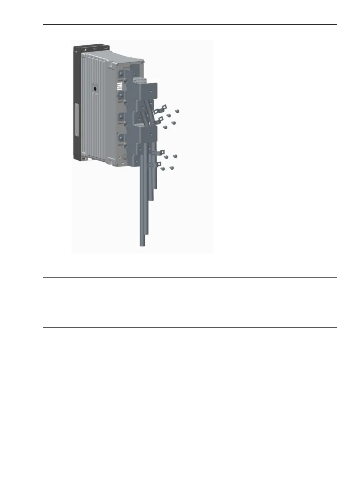
Figure 3-73
Clamps for Fixing the Cables
NOTICE
The isolation of the cables can be damaged if you are careless when mounting the clamps.
Noncompliance with the specified safety instructions means that material damage can occur.
²
Be carefull when mounting the clamps to protect the isolation of the cables.
²
Connect the delivered PE cable to the module or the base unit on the right of the LPIT module IO240. If
there are additional IO modules, you must connect their PE cables to the upper PE screw of the LPIT
module IO240. Siemens recommends using screws with 1.6-Nm torque.
Electronic Modules
3.2 Input and Output Modules of the Modular Devices
SIPROTEC 5, Hardware Description, Manual 121
C53000-G5040-C002-J, Edition 08.2020

 Loading...


