2.9 Backup Time Overcurrent Protection
101
7SD610 Manual
C53000-G1176-C145-4
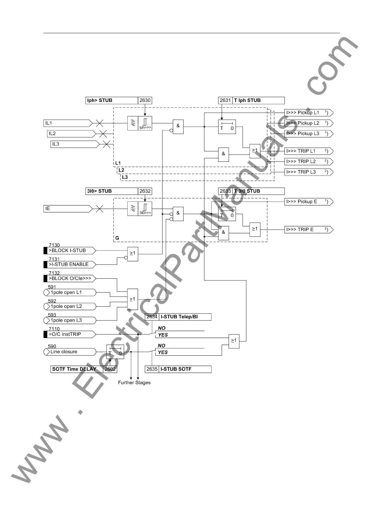
The I>>> stage can, however, also be used as a standard additional and independent
overcurrent stage, since it works independent of the other stages. In this case, the
enable input „>I-STUB ENABLE“ must be activated permanently (via a binary input
or CFC).
Figure 2-39 Logic diagram of the I>>> stage
1
) Output indications associated with the pickup signals are listed in Table 2-3
2
) Output indications associated with the trip signals are listed in Table 2-4
Directional, Definite
Time Overcurrent
Stage I>
The directional overcurrent stages follow the same principle as the non-directional
stages. However, triggering is not dependent on the result of the direction determina-
tion. Direction determination occurs via the measuring values and the respective di-
rectional characteristics.
www . ElectricalPartManuals . com

 Loading...


