2 Functions
100
7SD610 Manual
C53000-G1176-C145-4
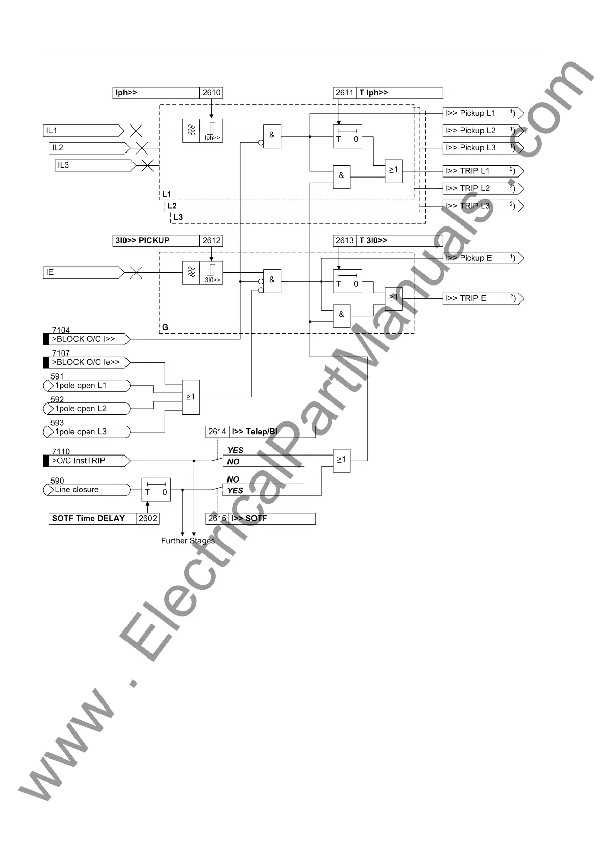
Figure 2-38 Logic diagram of the I>> stage
1
) Output indications associated with the pickup signals are listed in Table 2-3
2
) Output indications associated with the trip signals are listed in Table 2-4
Definite time over-
current stage I>
The logic of the overcurrent stage I> is the same as that of the I>> stages. In all ref-
erences Iph>> must merely be replaced with Iph> or 3I0>> PICKUP with 3I0>. Pa-
rameter 2624 I> Telep/BI is default as NO. In all other respects Figure 2-38 ap-
plies.
Additional Stage
I>>>
The additional definite time or instantaneous overcurrent stage I>>> has an extra
enable input (Figure 2-39) It is therefore also suitable e.g. as a stub protection or as
an emergency stage if the remaining stages are used as backup stages. The enable
input „>I-STUB ENABLE“ can be assigned to the output signal „Emer. mode“
(either via binary outputs and inputs or via the user-definable logic CFC functions).
The stage is then automatically active when the differential protection is not effective,
e.g. due to a data disturbance.
www . ElectricalPartManuals . com

 Loading...


