3 Mounting and Commissioning
276
7SD610 Manual
C53000-G1176-C145-4
Note
For a direct connection to DIGSI with interface RS232 jumper X111 must be plugged
in position 2-3.
If there are no external terminating resistors in the system, the last devices on a
RS485 bus must be configured via jumpers X103 and X104.
Table 3-7 Jumper settings of the Terminating Resistors of the RS485 interface on the
C-CPU-2 processor board
Note: Both jumpers must always be plugged in the same way!
Jumper X90 has no function. The factory setting is 1-2.
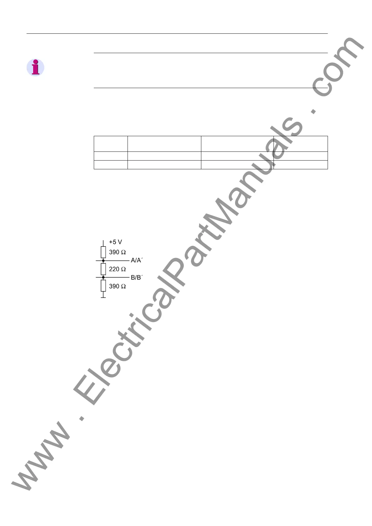
Terminating resistors can also be connected externally (e.g. to the terminal block). In
this case, the terminating resistors located on the RS485 or PROFIBUS interface
module or directly on the PCB of the processor board C-CPU-2 must be de-energized.
Figure 3-5 Termination of the RS485 interface (external)
Jumper Terminating resistor
closed
Terminating resistor open Presetting
X103 2-3 1-2 1-2
X104 2-3 1-2 1-2
www . ElectricalPartManuals . com

 Loading...


