3.1 Mounting and Connections
277
7SD610 Manual
C53000-G1176-C145-4
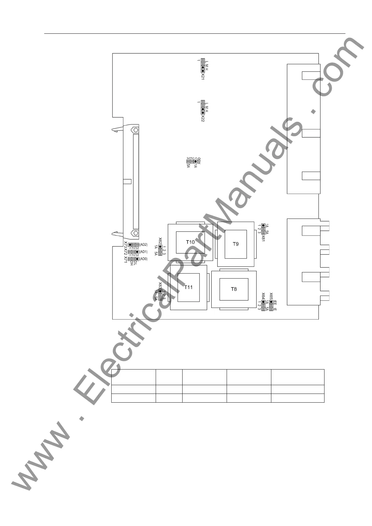
Input/Output Board
C-I/O-11
Figure 3-6 C-I/O-11 input/output board with representation of jumper settings required for
checking configuration settings
Table 3-8 Jumper settings for Control Voltages of the binary inputs BI6 and BI7 on the
input/output board C-I/O-11
1)
Factory settings for devices with power supply voltages of 24 VDC to 125 VDC
2)
Factory settings for devices with power supply voltages of 110 VDC to 250 VDC
3)
Use only with control voltages 220 to 250 VDC and 250 VAC
The set nominal current of the current input transformers are checked on the input/out-
put board C-I/O-11. The jumpers X60 to X64 must all be set to the same rated current,
Binary input Jumper 17 V Threshold
1)
73 V Threshold
2)
154 V Threshold
3)
BI6 X21 L M H
BI7 X22 L M H
www . ElectricalPartManuals . com

 Loading...


