3.1 Mounting and Connections
275
7SD610 Manual
C53000-G1176-C145-4
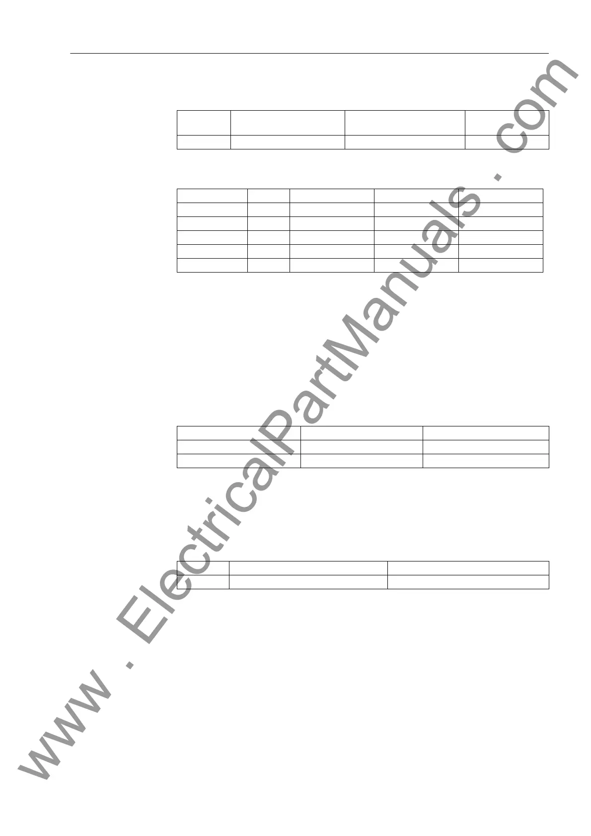
Table 3-3 Jumper setting of the quiescent state of the Life Contact on the processor
board C-CPU-2
Table 3-4 Jumper setting of the Control Voltages of the binary inputs BI1 to BI5 on the C-
CPU-2 processor board
1)
Factory settings for devices with power supply voltages of 24 VDC to 125 VDC
2)
Factory settings for devices with power supply voltages of 110 VDC to 250 VDC and 115 VAC
3)
Use only with control voltages 220 or 250 VDC and 250 VAC
By repositioning jumpers the interface RS485 can be modified into a RS232 interface
and vice versa.
Jumpers X105 to X110 must be set to the same position.
Table 3-5 Jumper settings of the integrated RS232/RS485 Interface on the C-CPU-2 pro-
cessor board
The jumpers are preset at the factory according to the configuration ordered.
With interface RS232 jumper X111 is needed to activate CTS which enables the com-
munication with the modem.
Table 3-6 Jumper setting for CTS (Clear To Send, flow control) on the C-CPU-2 proces-
sor board
Jumper setting 2-3: The connection to the modem is usually established with a star
coupler or fibre-optic converter. Therefore the modem control signals according to
RS232 standard DIN 66020 are not available. Modem signals are not required since
the connection to the SIPROTEC 4 devices is always operated in the half-duplex
mode. Please use the connection cable with order number 7XV5100-4.
Jumper setting 1-2: This setting makes the modem signals available, i. e. for a direct
RS232-connection between the SIPROTEC 4 device and the modem this setting can
be selected optionally. We recommend to use a standard RS232 modem connection
cable (converter 9-pin to 25-pin).
Jumper Open in the quiescent
state
Closed in the quiescent
state
Presetting
X40 1-2 2-3 2-3
Binary Inputs Jumper 17 V Threshold
1)
73 V Threshold
2)
154 V Threshold
3)
BI1 X21 1-2 2-3 3-4
BI2 X22 1-2 2-3 3-4
BI3 X23 1-2 2-3 3-4
BI4 X24 1-2 2-3 3-4
BI5 X25 1-2 2-3 3-4
Jumper RS232 RS485
X103 and X104 1-2 1-2
X105 to X110 1-2 2-3
Jumper /CTS from Interface RS232 /CTS Controlled by /RTS
X111 1-2 2-3
www . ElectricalPartManuals . com

 Loading...


