3 Mounting and Commissioning
280
7SD610 Manual
C53000-G1176-C145-4
Table 3-10 Replacement modules for interfaces
The ordering numbers of the exchange modules are listed in Appendix A.1.
RS232 Interface Interface RS232 can be modified to interface RS485 and vice versa (see Figures 3-8
and 3-9).
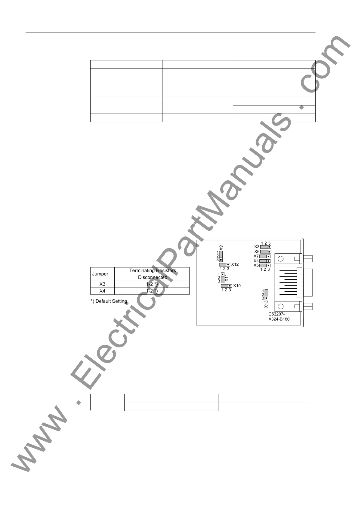
Figure 3-7 shows the C-CPU-2 PCB with the layout of the modules.
The following figure shows the location of the jumpers of interface RS232 on the inter-
face module.
Surface-mounted devices with fibre optics connection have their fibre optics module
fitted in the console housing on the case bottom. The fibre optics module is controlled
via an RS232 interface module at the associated CPU interface slot. For this applica-
tion type the jumpers X12 and X13 on the RS232 module are plugged in position 2-3.
Figure 3-8 Location of the jumpers for configuration of RS232
Terminating resistors are not required for RS232. They are disconnected.
Jumper X11 is used to activate the flow control which is important for the modem com-
munication.
Table 3-11 Jumper setting for CTS (Clear To Send, flow control) on the interface module
1)
Default Setting
Interface Mounting location / port Exchange Module
System interface
B
Only interface modules that can
be ordered in our facilities via the
order key (see Appendix, Section
A.1).
Service Interface
CRS232
RS485
Protection Data Interface D FO5, FO6; FO17 to FO19
Jumper /CTS from Interface RS232 /CTS controlled by /RTS
X11 1-2 2-3
1)
www . ElectricalPartManuals . com

 Loading...


