3.1 Mounting and Connections
281
7SD610 Manual
C53000-G1176-C145-4
Jumper setting 2-3: The connection to the modem is usually established with a star
coupler or fibre-optic converter. Therefore the modem control signals according to
RS232 standard DIN 66020 are not available. Modem signals are not required since
the connection to the SIPROTEC 4 devices is always operated in the half-duplex
mode. Please use the connection cable with order number 7XV5100-4.
Jumper setting 1-2: This setting makes the modem signals available, i. e. for a direct
RS232-connection between the SIPROTEC 4 device and the modem this setting can
be selected optionally. We recommend to use a standard RS232 modem connection
cable (converter 9-pin to 25-pin).
Note
For a direct connection to DIGSI with interface RS232 jumper X11 must be plugged in
position 2-3.
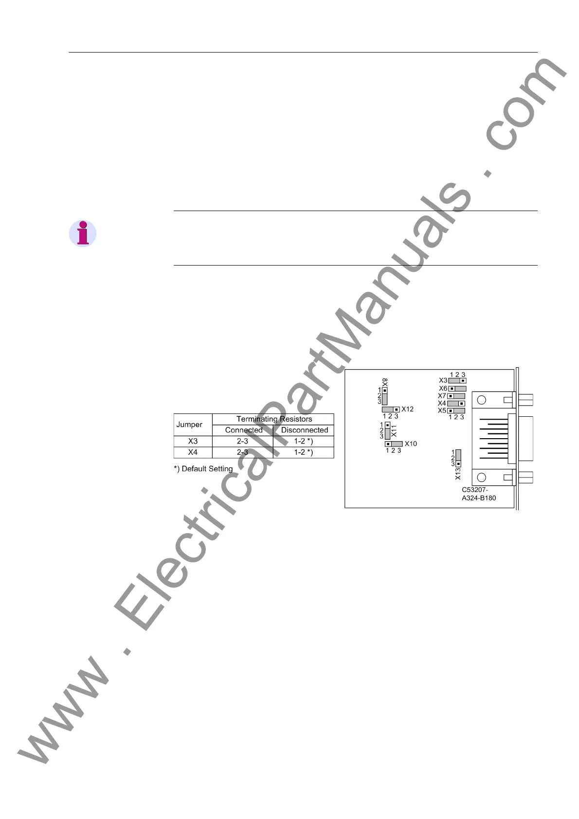
RS485 Interface The following figure shows the location of the jumpers of interface RS485 on the inter-
face module.
Interface RS485 can be modified to interface RS232 and vice versa, according to
Figure 3-8.
Figure 3-9 Position of terminating resistors and the plug-in jumpers for configuration of the
RS485 interface
www . ElectricalPartManuals . com

 Loading...


