3 Mounting and Commissioning
282
7SD610 Manual
C53000-G1176-C145-4
Profi-
bus/DNP/MODBUS
Interface
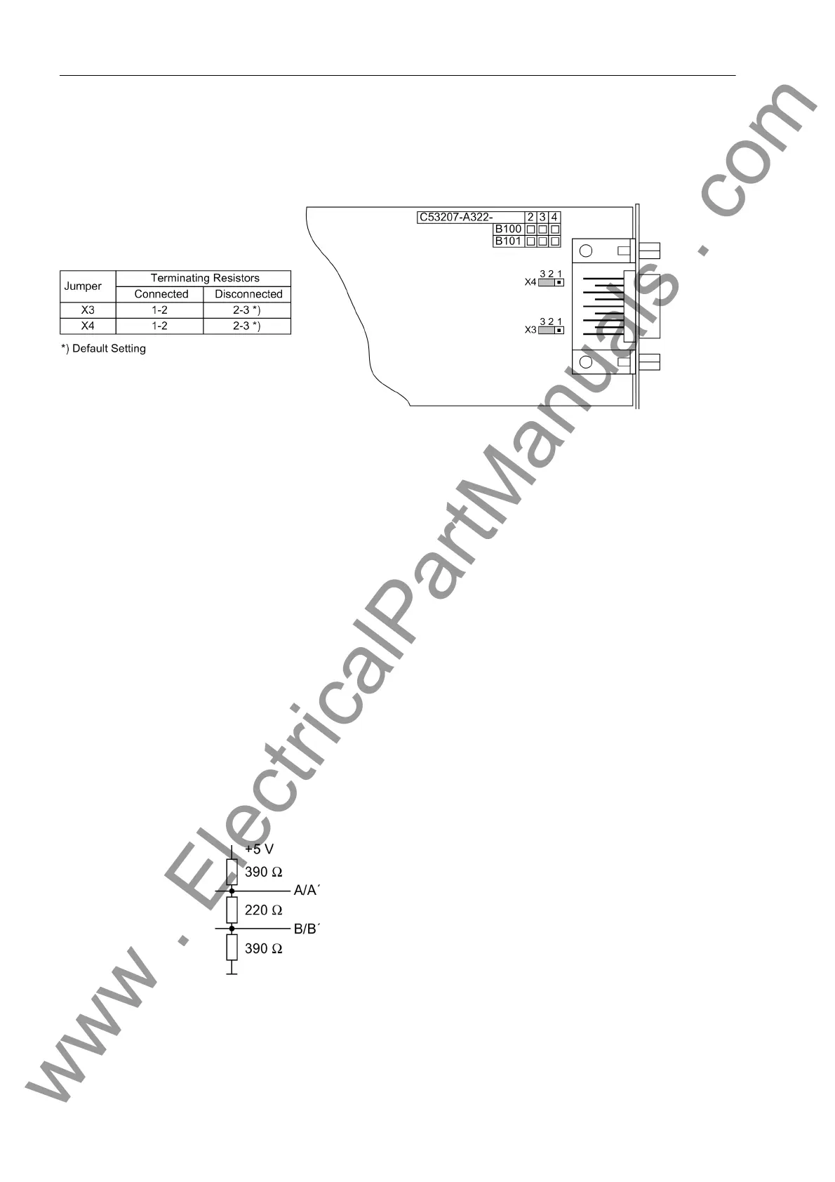
Figure 3-10 Location of the jumpers for configuring the terminating resistors (PROFIBUS, DNP and MODBUS interface)
EN100 Ethernet
Module (IEC 61850)
The Ethernet interface module has no jumpers. No hardware modifications are re-
quired to use it.
Termination Bus-capable interfaces always require a termination at the last device on the bus, i.e.
terminating resistors must be connected. On the 7SD610 device, this concerns the
variants with RS485 or PROFIBUS7/DNP/MODBUS interfaces.
The terminating resistors are located on the interface module which is on the proces-
sor module C-CPU-2 (no.1 in Figure 3-3) or directly on the PCB of the processor
module C-CPU-2 (see Section „Processor module C-CPU-2“, Table 3-7).
The interface modules are displayed in Figure 3-9 and in Figure3-10.
For the configuration of the terminating resistors both jumpers have to be plugged in
the same way.
On delivery the jumpers are set so that the terminating resistors are disconnected.
The terminating resistors can also be implemented outside the device (e.g. at the ter-
minal block), see Figure 3-11. In this case, the terminating resistors located on the in-
terface module or directly on the PCB of the processor board C-CPU-2 must be dis-
connected.
Figure 3-11 Termination of the RS485 Interface (External)
www . ElectricalPartManuals . com

 Loading...


