Multi-sector installation
43
Building Technologies A6V10257473_b_en_--.doc
Fire Safety & Security Products 01.2010
8.2 Multiple flooding zones modules overview
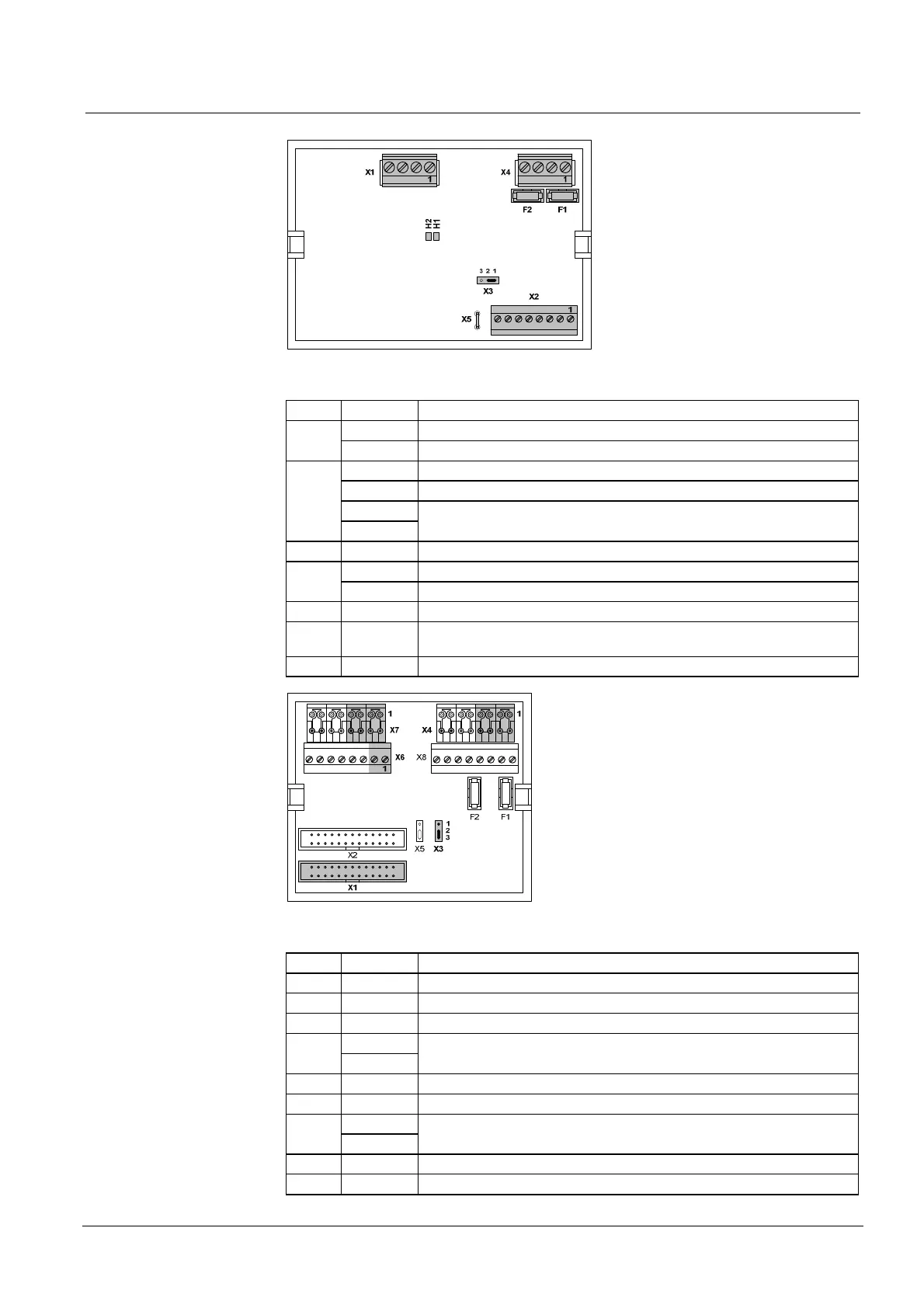
Fig. 29 XCA1031, multiple flooding zones common module
Mark Terminals Function
1 (+) / 2 (–) 24 V power supply input N° 1 X1
3 (+) / 4 (–) 24 V power supply input N° 2
1 (–) / 2 (+) Extinguishing agent monitoring
3 (–) / 4 (+) Inter blocking
5 (–) / 7 (+)
X2
6 (–) / 8 (+)
RS485 bus
X3 — RS485 bus configuration jumper (see paragraph 8.3)
1 (+) / 2 (–) Actuator 1 (indicated polarities are control polarities) X4
3 (+) / 4 (–) Actuator 2 (indicated polarities are control polarities)
X5 — Ground connection
H1 / H2 — 24V power supply indications (H1: power supply input 1, H2: power supply
input 2)
F1 / F2 — 1 AF fuse protection for actuator lines 1 (F1) and 2 (F2)
Fig. 30 XCA1030, multiple flooding zones individual module
Mark Terminals Function
X1 — XCM1002 main board flat cable connection
X2 — Not used
X3 — RS485 bus configuration jumper (see paragraph 8.3)
1 (+) / 3 (–) X4
2 (+) / 4 (–)
RS485 bus
X5 — Not used
X6 1 (+) / 2 (–) Selector valve position monitoring
1 (+) / 3 (–) X7
2 (+) / 4 (–)
Inter blocking
X8
F1 / F2 — Unused fuses

 Loading...

