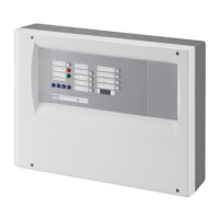
Features
21
Building Technologies A6V10257473_b_en_--.doc
Fire Safety & Security Products 01.2010
5 Features
Primary source (mains)
Voltage
Current
Power
115 / 230 VCA +10 …-15% – 50 / 60 Hz
1.75 A max.
150 VA max.
Secondary source (batteries)
Connectable batteries
Voltage
Charging current max.
Internal resistance max.
Deep discharge (disconnection threshold)
2 x 12 V / 4.5 … 17 Ah
23.4 … 27.6 V
1.3 A (with temperature compensation)
1 Ω
20 V +/-3%
Power supply (FCP1004-E)
Output
Voltage
Max. available current
Min. current
Power
Switching frequency / Ripple
27.3 V +/- 0.3 V (25°C)
Imax a : 2 A (batteries loading)
Imax b : 3.5 A (batteries loaded)
0.05 A
105 W max.
132kHz / 70 mVpp max.
XCM1002
Input voltage
Current consumption
I/Os security level
22.5 … 27.6 V (25°C)
190 mA max. without primary source
SELV (Safety Extra Low Voltage)
Detection lines
Type / number of detectors
Compatible detectors
End of line element (EOL)
Standby condition voltage / current
Alarm condition voltage / current
Line resistance
Collective / 32 max. (according to detector type)
Siemens (Algorex, Sinteso, Synova)
Transzorb 18 V (P6KE18CA)
17.1 … 19.3 V (fixed by EOL) / 11 mA max.
5.5 … 16.5 V / 11 … 57.1 mA max.
80 Ω max.
Manual release line
Type / number of manual actuators
End of line element (EOL)
Voltage / standby line current
Voltage / alarm line current
Line resistance
DM1103-L / 32 max.
Transzorb 18 V (P6KE18CA)
17.1 … 19.3 V (fixed by EOL) / 11 mA max.
5.5 … 16.5 V / 11 … 57.1 mA max.
80 Ω max.
Monitored inputs
4
Activation resistance
End of line element (EOL)
Line resistance
680 Ω or 1.2 kΩ
3.3 kΩ resistance
80 Ω max.
Control inputs (non
monitored)
4 Activation +24 V, via contact
Outputs 1 to 3
Control voltage / current
End of line element
24 V / 1 A max.
3.3 kΩ resistance
Monitored control outputs
Outputs 1 to 3
Outputs 4 and 5
Control voltage / current
End of line element
24 V / 2 A max.
No EOL (line calibration)
Driver outputs
8 (programmable) 24 V / 40 mA max.
Relay outputs (contacts)
5 (4 programmable) 30 V / 1 A max. / NO or NC
XCM1002
Inputs - outputs type / section
Plug-in screw terminal blocks
2.5 mm
2
max. (X5, X5, X7)
1.5 mm
2
max. (all others)
Connections
FCP1004-E
mains input type / section
Plug-in screw terminal block / 2.5 mm
2
max.
Environmental conditions
Operating / Storage temperature
Humidity relative at 40
±
2° C
-5 ... +40° C / -20 ... +60° C
93% max., without condensation
XC1001-A Cabinet / Protection index
Color
Dimensions (l x h x p) / Weight
Metal frame with plastic cover / IP30
RAL9003 (cover), RAL9006 (user interface)
370 x 286 x 90 mm / 4.1 kg
XC1005-A Cabinet / Protection index
Color
Dimensions (l x h x p) / Weight
Metal case with plastic cover / IP40
RAL9003 (cover), RAL9006 (user interface)
505 / 375 / 125 mm / 6.5 kg
Mechanical data
XC1003-A Cabinet / Protection index
Color
Dimensions (l x h x p) / Weight
Rack 19’’ 4U / IP30
RAL9006
482.6 (19’’) x 177.8 (4U) x 187 mm / 6.6 kg
Conformity
EN 12094-1, EN 54-2/A1, EN 54-4/A2 —

 Loading...