Overview
18
Building Technologies A6V10257473_b_en_--.doc
Fire Safety & Security Products 01.2010
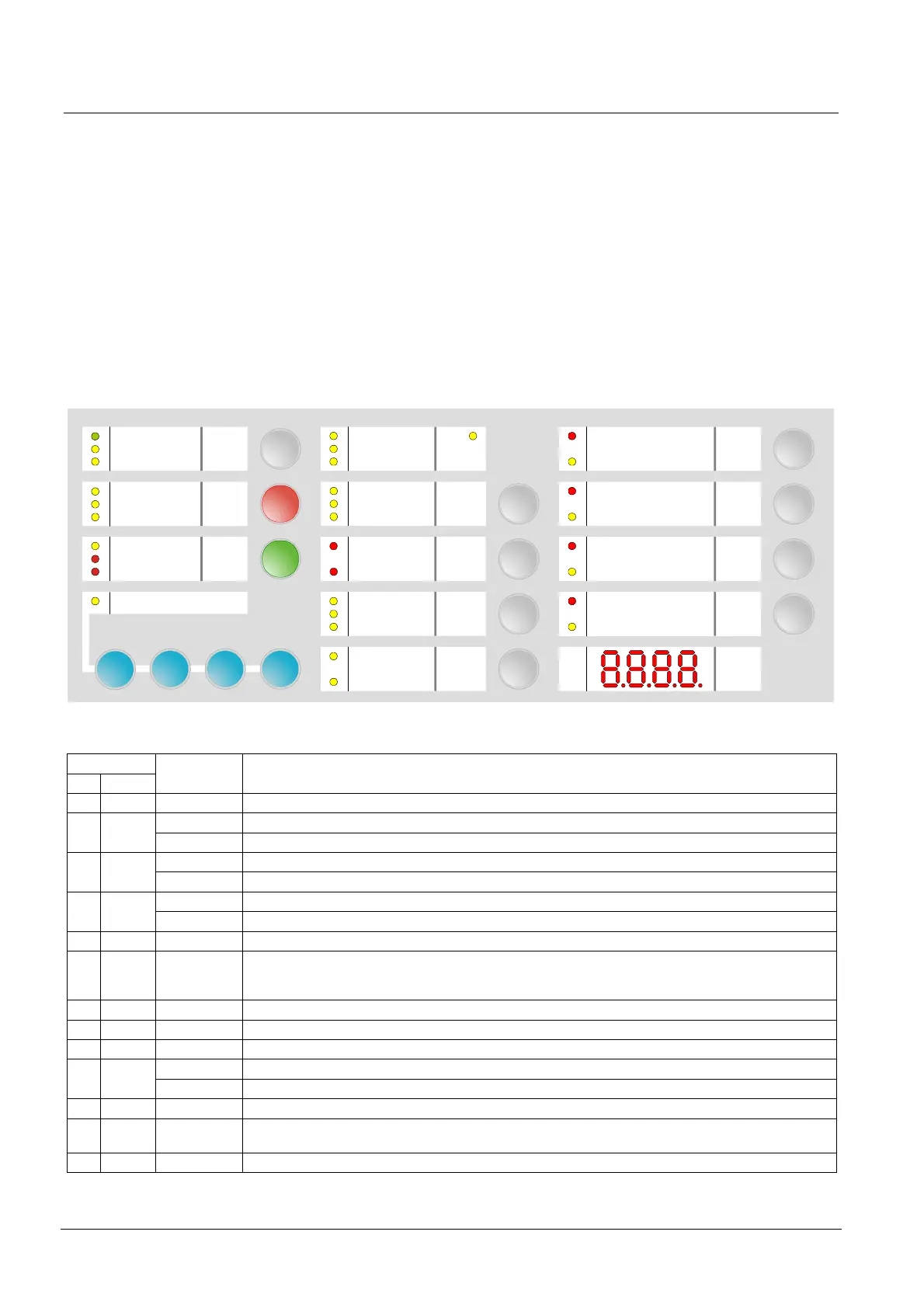
4.6 User interface
All display and control elements, except 4-digit display for XC1001-A and XC1003-A
versions, are accessible to the user:
- Led 1 to 32 indicators for operating condition,
- Keys 1 to 15 allowing :
operating access
operation (reset, off, test, etc)
system test
user functions programming
- 4-digit display showing:
programming steps and options
pre-warning time count down
other information’s (calibration states, alarm counter, etc)
System ON
Silence
buzzer
Silence
Re-sound
Sounders
Automatic blocked
Activated
Mode
Operating access
Earth fault
System fault
Disable
Fault
Manual blocked
Manual release
Released
Detector Zone 1
………………………………….
Mechanical blocked
Loss of agent
Incorrect status
Emergency
hold
Sounders
Fire controls
Disable
Enable
Detector test
Fire alarm
Remote transmission
Disable
Test
Enable
Detector Zone 2
……………………………………
Detector Zone 3
……………………………………
432
1
5 2
1
2
4
5
6
7
8
9
10 19
21
11
12
13
14
15
16
17
24
26
28
30
32
25
27
29
31
8
10
12
13
9
6
7
14
15
Disable
Test
Enable
Disable
Test
Enable
Disable
Test
Enable
3
18
Power supply
Reset
RT-fault
RT-alarm
22
23
11
20
Actuators
Led test
Disable
Enable
Fig. 6 XC10xx-A, user interface
Indicators
N° Color
State Description
1 Green Fixed The control panel is in operation
Fixed The control panel is not able to function any more 2 Yellow
Fast Fault on at least one component in the system (see paragraph 14.2 for the detail)
Slow Mains fault 3 Yellow
Fast Batteries fault
Fixed Microprocessor fault 4 Yellow
Slow Jumper buzzer (X3 - XCM1002 board) not connected (remainder)
5 Yellow Fast At least one component connected to the control panel is grounded
6 Yellow Fixed – At least one component in the system is disabled
– Calibration in progress or error
– Programming in progress
7 Yellow Slow At least one detection zone and/or extinguishing manual control is being tested
8 Red Fixed At least one detection zone is in alarm
9 Red Fixed Remote transmission activated (*)
Fixed Level 2 operating access granted 10 Yellow
Slow System test activated
11 Yellow Fixed Mechanical blocking device is in the blocked position
12 Yellow Fast – Mechanical blocking device is in a wrong position
– Selector valve is in a wrong position (used for multi-sector applications)
13 Yellow Fast Loss of agent
(*) According to programming

 Loading...

