Multi-sector installation
44
Building Technologies A6V10257473_b_en_--.doc
Fire Safety & Security Products 01.2010
8.3 Multiple flooding zones modules assembly and connection
Multiple flooding zones modules are mounted on a DIN rail:
- XCA1031 : in the 19" cabinet where XC1003-A control units are installed
- XCA1030 : in each XC1003-A (see Fig. 3)
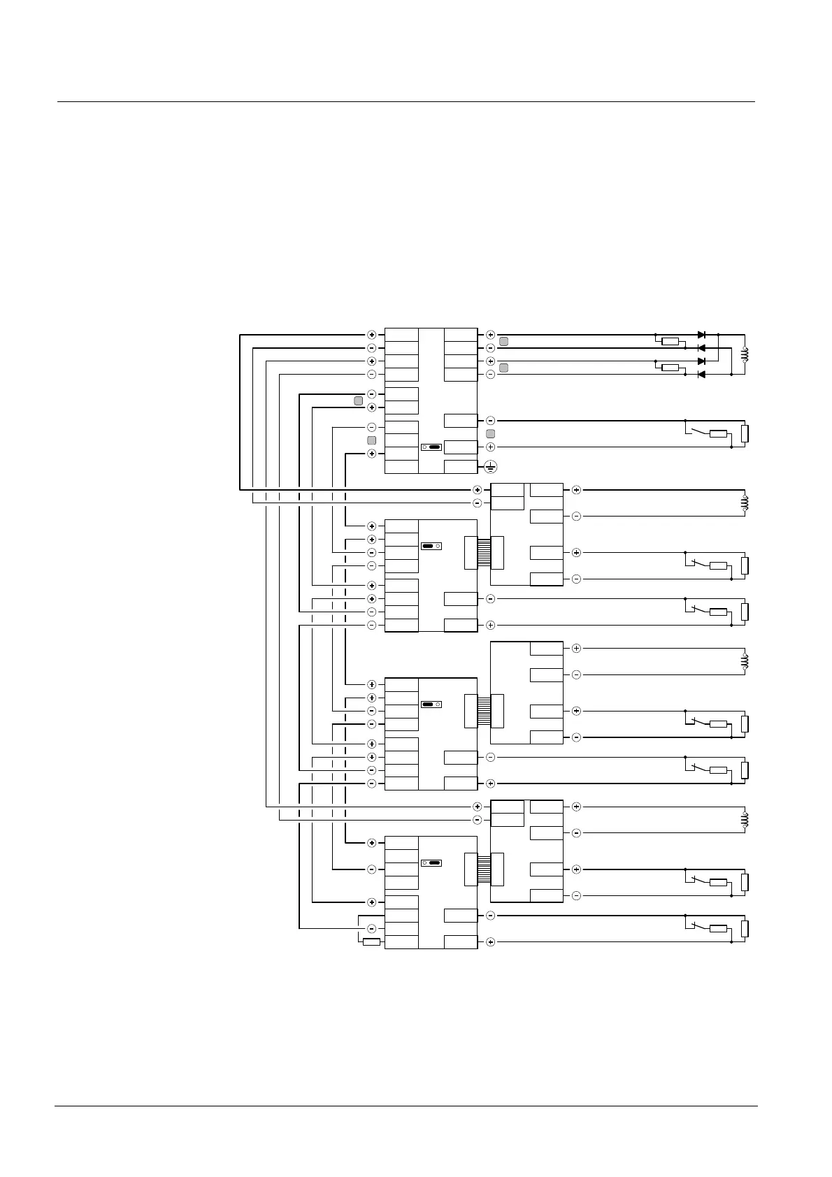
The drawing below shows a connection example between XCA1030 modules and
the XCA1031 for a 3 flooding zones installation.
Note: to ensure power supply redundancy, connect the 24V power supply to the
XCA1031 module from two XC10 panels. Otherwise, a fault message is displayed
on all XC10 panels.
Inter-blocking
Selector valve position / sector 1
Power supply 24 V N°1
Power supply 24 V N°2
Loss of agent
XCA1031
XCA1030 / 1
XCM1002 / 1
X30
1.2 kΩ
3.3 kΩ
Sector valve / sector 1
1.2 kΩ
3.3 kΩ
Discharged / sector 1
1.2 kΩ
3.3 kΩ
Selector valve position / sector 2
1.2 kΩ
3.3 kΩ
XCA1030 / 2
X1
XCA1030 / n
X7 - 1
X7 - 2
X7 - 3
X7 - 4
X6 - 1
X6 - 2
X4 - 1
X4 - 2
X4 - 3
X4 - 4
X1
X4 - 1
X4 - 2
X4 - 3
X4 - 4
X7 - 1
X7 - 2
X7 - 3
X7 - 4
X6 - 1
X6 - 2
X4 - 1
X4 - 2
X4 - 3
X4 - 4
X1
X7 - 1
X7 - 2
X7 - 3
X7 - 4
3.3 kΩ
X3
1 2 3
X3
1 2 3
X6 - 3
X6 - 4
X9 - 1
X9 - 2
X3
1 2 3
X6 - 1
X6 - 2
Selector valve position / sector 3
1.2 kΩ
3.3 kΩ
X3
1 2 3
C
X2 - 3
X2 - 4
X2 - 5
X2 - 6
X2 - 7
X2 - 8
X4 - 1
X4 - 2
X4 - 3
X4 - 4
X2 - 1
X2 - 2
X5
A
RS485
D
X5 - 4
X5 - 3
Control valve 1
Control valve 2
3,3 kΩ
X1 - 2
X1 - 3
X1 - 4
X1 - 1
B
B
3,3 kΩ
XCM1002 / 2
X30
Sector valve / sector 2
Discharged / sector 2
1.2 kΩ
3.3 kΩ
X6 - 3
X6 - 4
X9 - 1
X9 - 2
XCM1002 / n
X30
Sector valve / sector 3
Discharged / sector 3
1.2 kΩ
3.3 kΩ
X6 - 3
X6 - 4
X9 - 1
X9 - 2
X5 - 4
X5 - 3
Jumpers for RS485 configuration (X3) must be on position 2 / 3 for the first and the last modules, on 1 / 2 for the others (see example above).
Fig. 31 XC1003-A, multi-sector installation connection

 Loading...

