Maintenance
66
Building Technologies A6V10257473_b_en_--.doc
Fire Safety & Security Products 01.2010
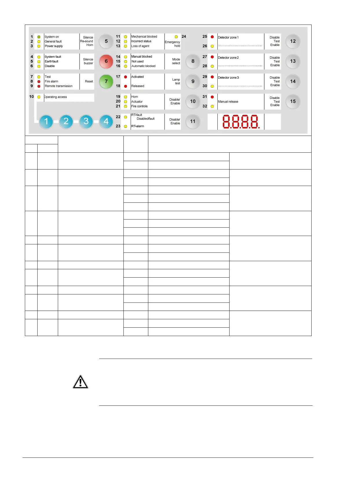
LED
N° Color
Designation State Significance
Fixed SC 20 Yellow Actuators
Slow OL
Monitored output 2
Fixed SC 21 Yellow Fire controls
Slow OL
Monitored output 3
Fixed SC
Slow OL
22 Yellow RT-Fault
Fast Calibration error
Monitored output 4
Fixed SC
Slow OL
23 Yellow RT-Alarm
Fast Calibration error
Monitored output 5
25 Red Zone 1 Fixed Alarm < 15 s after reset
Fixed SC 26 Yellow Zone 1
Slow OL
Detection line 1
27 Red Zone 2 Fixed Alarm < 15 s after reset
Fixed SC 28 Yellow Zone 2
Slow OL
Detection line 2
29 Red Zone 3 Fixed Alarm < 15 s after reset
Fixed SC 30 Yellow Zone 3
Slow OL
Detection line 3
31 Red Manual release Fixed Enabled < 15 s after reset
Fixed SC 32 Yellow Manual release
Slow OL
Manual release line
CAUTION
Any electrical fault (break or short circuit) on the following lines may have a
direct consequence on the extinguishing process, or in some cases prevent it.
- Detector lines
- Manual release line
- Monitored control output 1 to 5
- Monitored inputs 1 to 4
It is imperative to fix any fault in a short delay in order to not jeopardize an
extinguishing process.

 Loading...

