SIGLENT
46 SDS1000CML/CNL/DL Service Manual
Check the Power Supply
Before performing the power supply testing procedure, please make sure that
the oscilloscope is grounded through the protective lead of the power cord.
take care not to touch or even disassemble the power supply module without
any safety precautions, or you may probably suffer from electric shock or burn.
Here are procedures for testing the power supply:
1. Disconnect the power cord of the oscilloscope and then check whether the
fuse has been burnt out.
2. Remove metallic cover of the power supply module using a driver, and then
connect the power cord.
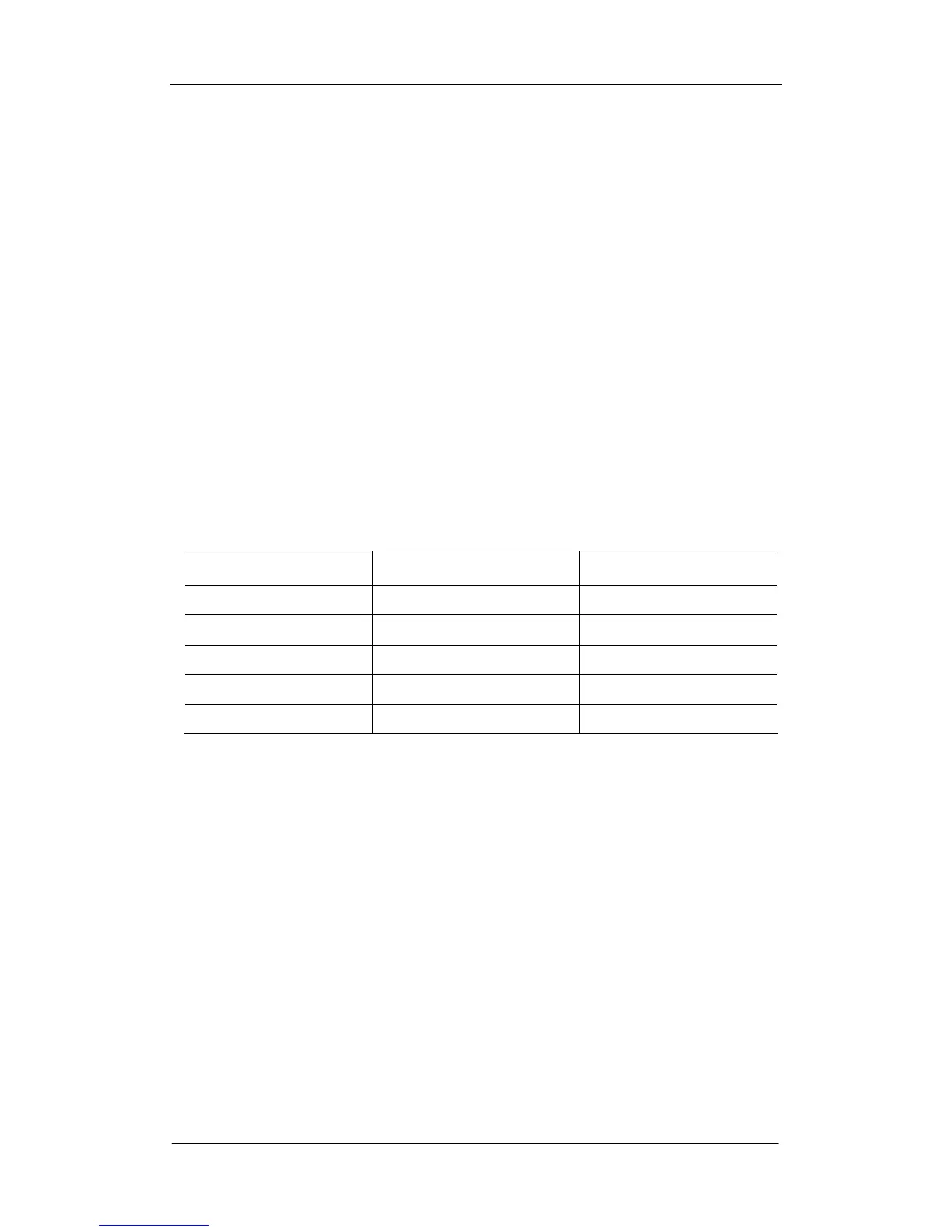
3. Focus at the Power Connector which contains 12 pins from Pin1 to Pin12 on
the main board. You can test voltages provided by power supply at these
points to check whether the voltage values are within specified range using a
digital multimeter. The voltage parameters to be tested are listed in table
below:
Table 6-2 Voltage parameters of the power supply module
Voltage value(V) Pin Error
0 (GND) Pin1, Pin5, Pin8, Pin12 NULL
15 Pin2 5%
6.3 Pin3, Pin4 10%
3.3 Pin6, Pin7 5%
-9 Pin9 10%
If each tested voltage value is within the spec range referring to the table
above, then check the power-supply ripple using an oscilloscope. If the
ripple appears small, then the power supply works normally. Otherwise, it
proves to be faulted;
If there is at least one tested voltage value beyond the spec range, please go
to the next step.
4. Disconnect the cable connected to main board, and then perform the testing
procedures as the table above again:
If each tested voltage value is within spec range referring to the table above,
then it is the failure of the main board load that leads to problematic power
supply. Continuous checking or even replacing the main board is required
for further test.
If there is at least one tested voltage value beyond the spec range, then the
power supply module proves faulted and a new one is needed. For safety,
please do not disassemble the power supply module by yourself.