SIGLENT
SDS1000CML/CNL/DL Service Manual 47
Check the Main Board
If you want to remove the main board from the metal shelf inside the
oscilloscope, you’d better place it on a clean, insulated mat. In addition, to
avoid some chips or components on the main board being damaged for
overheating, it is essential to cool the main board whenever possible using a
fan. Here are procedures for testing the main board:
1. Several kinds of connectors including Fan Connector, LCD Connector and
Keypad Connector are located on the main board. Check if all these
connectors are connected properly.
2. Make sure that the connectors on the main board are properly connected,
then connect the power supply module cable to appointed place of the main
board, lastly connect the oscilloscope power cord and turn on the
oscilloscope. Check if the voltage values at all test points are within the spec
range using a digital multimeter. The voltage parameters to be tested are
listed in table below:
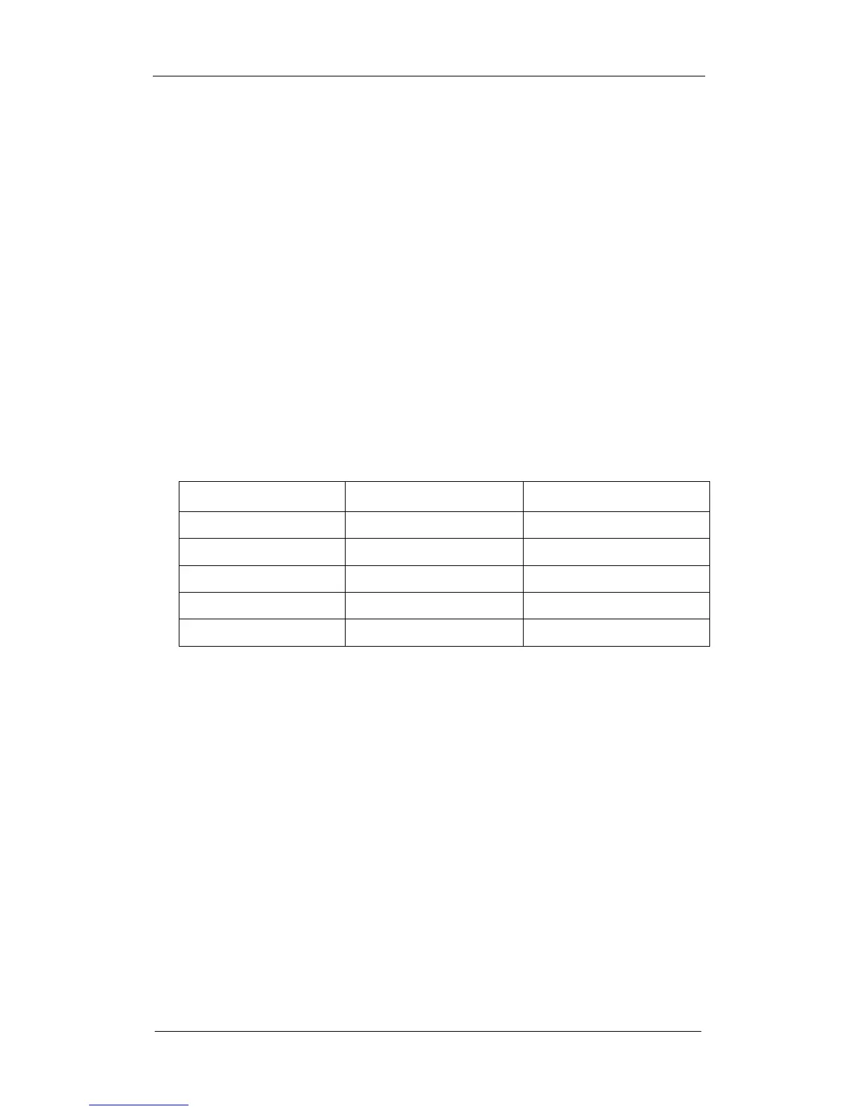
Table 6-3 Voltage parameters of the main board
Components tested
Voltage (V) Error (V)
C191 -5 ±0.1
CL1 5 ±0.1
CL2 5 ±0.1
CL3 2.5 ±0.1
CL7 1.25 ±0.1
If there is at least one tested voltage value beyond the spec range referring
to the table above, please turn off the oscilloscope and cut the power
immediately to avoid damage to the chips or even the main board due to its
abnormal working. Otherwise, you need to replace a new main board as a
consequence.
If each tested voltage value is within the spec range, please go to the next
step.
3. Check if the Clock on the main board works normally using an oscilloscope.
Focus at the test clock T53 marked with “100M Clock” on the main board
drawing.
If the clock measured is not 100M, then the failure may come from the main
board, a new one is required necessary.
If the clock measured is 100M, then go on to test if the clock T4 is 25MHz. If
it is, then the main board proves normal. Or you need to return the
oscilloscope to manufacturer to have it repaired by qualified personnel.