StreamCaster 4000 series MIMO Radio User Manual 9/2/20
10017C000 Silvus Technologies Confidential Page
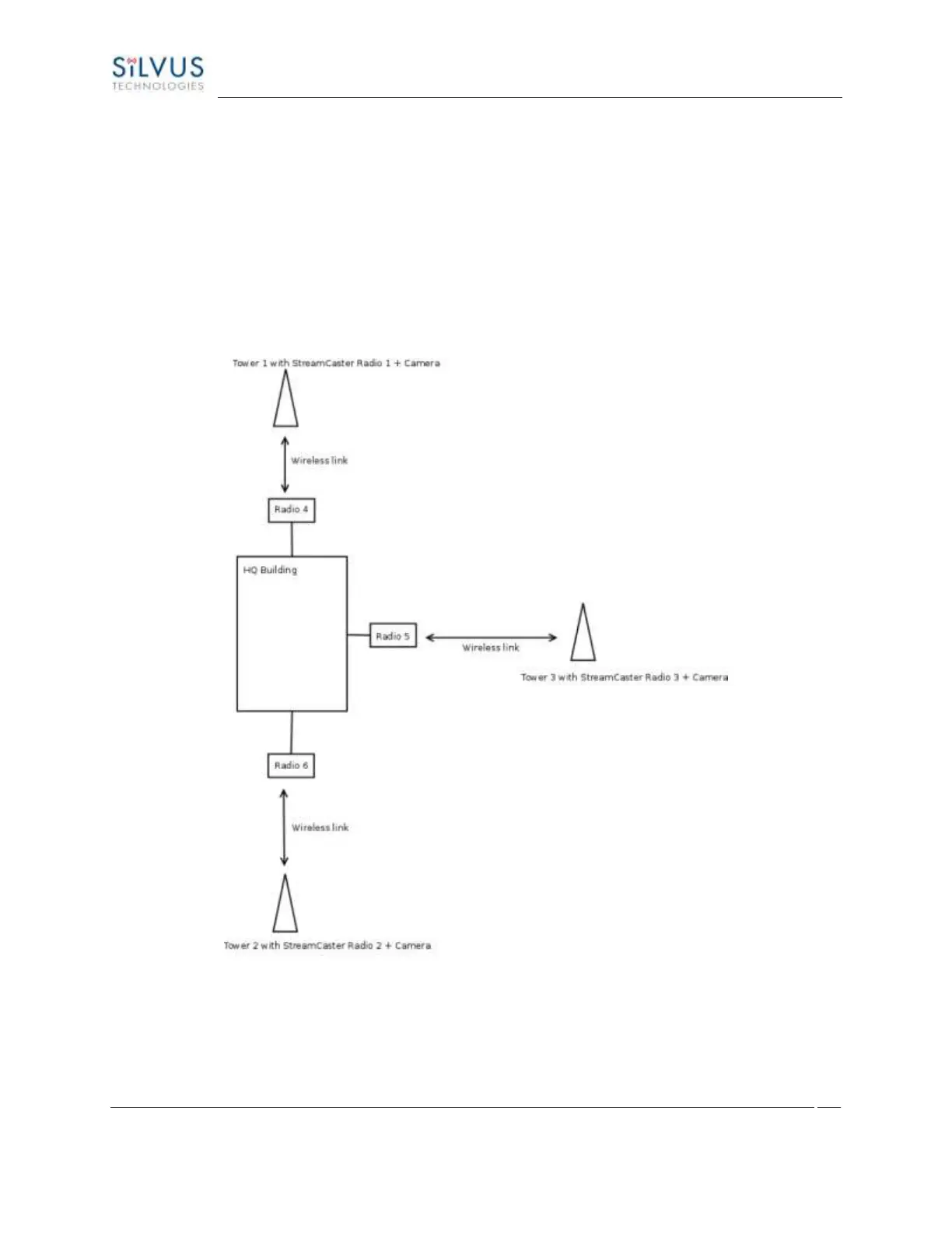
conserve air bandwidth and possible interference to other users, we want video data to go through the
high-speed LAN backbone as much as possible. The below diagram shows the scenario.
Towers 1-3 are equipped with IP cameras attached to StreamCaster radios 1-3. Radios 4-6 are mounted
on three sides of the HQ building with their Ethernet interfaces connected to the high-speed LAN. Tower
1 can only communicate wirelessly with radio 4, Tower 3 with radio 5 and Tower 2 with radio 6. Video
from Tower 1 will flow wirelessly to radio 4, then via the LAN backbone to the HQ viewer which is also
attached to the LAN backbone. Even though the radios 4-6 may communicate wirelessly, they will choose
to do so via the LAN backbone.
Figure 87 LAN Backbone Example