StreamCaster 4000 series MIMO Radio User Manual 9/2/20
10017C000 Silvus Technologies Confidential Page
Figure 38 Silvus StreamScape Network Topology Page
The network topology provides the user with real-time visual feedback of the network. Users will be able
to determine several network characteristics at a glance with the following features:
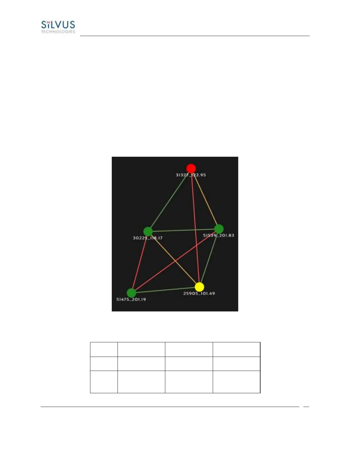
• Color Coded Link Health – Color coding of each link in the network allows the user to quickly
identify the weak links within a network. A link between two nodes will transition from green to
yellow to red as the link weakens while also displaying the SNR of the link. This can be seen in
Figure 39 Example Network Topology.
• Route Health – The Silvus StreamScape Utility will alert the user when too many packets are being
routed through a single node. In such cases, a node will change from green to yellow to red as the
packet queue increases (see ‘31327_122.95’ and ‘25905_101.49’ in Figure 39 Example Network
Topology). This will allow the user to recognize the issue and configure the network accordingly.
Table below also shows the values for each scenario.
Figure 39 Example Network Topology