page 59 579-1150 Rev M
4010ES IDNAC Fire Alarm System Installation Guide
Table 32: AUX/NAC wiring specification
Voltage
rating
24V special application
Rating 2A, maximum.
Wiring
gauge
18 AWG (min.)
to 12 AWG (max.).
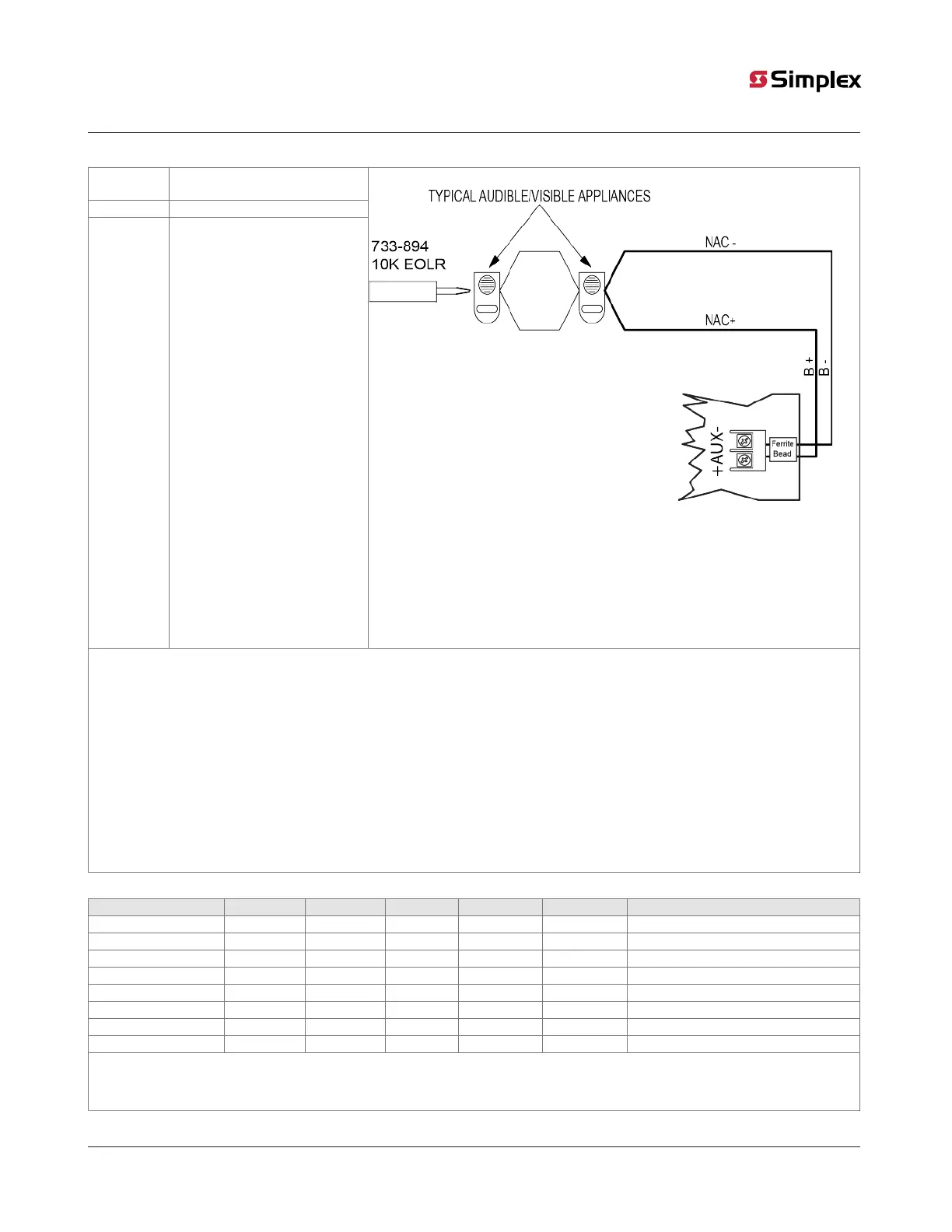
Figure 48: Simple NAC wiring
Wiring Notes:
1. All wiring from the AUX/NAC is power limited.
2. Conductors must test free of all grounds and stray voltages before connection to appliances and panel.
3. Terminate Class B NACs as shown using 733- 894. For Canadian applications, mount end-of-line resistor to Simplex-US Model 431537
EOL plate in accordance with ULC-S527.
4. If circuit is terminated with a 10k EOLR, at the terminals, remove this resistor before wiring.
5. If wiring is routed outside the building, use of a listed secondary protector is required. Use Simplex 2081- 9028 or 2081-9044. A
protector must be installed at each building exit/entrance. Each 2081-9028 adds 0.2 ohms wiring resistance. 2081-9044 adds 6 ohms
wiring resistance, and will greatly reduce wiring distance.
6. External wiring from the auxiliary power tap (AUX) is not supervised unless an end-of-line relay is wired to auxiliary power, and
normally open contacts are monitored by the FACU (IDNet device or IO point). Relay current must be considered as part of the load.
When only addressable devices are connected to the auxiliary power tap, an end-of-line relay is not required because the power for
the addressable devices is supervised due to the device being addressable. The preceding configurations provide AUX Power Class B.
7. Install a ferrite bead close to the AUX field wiring terminals for FCC compliance, as shown in Figure 48. Order separately as needed
(order kit 4100-5129).
Table 33: NAC wiring limits
Alarm current 20 AWG 18 AWG 16 AWG 14 AWG 12 AWG Line resistance (Ohms)
0.25 617 ft 981 ft 1560 ft 2480 ft 3944 ft 14.00
0.50 308 ft 490 ft 780 ft 1240 ft 1972 ft 7.00
0.75 206 ft 327 ft 520 ft 827 ft 1315 ft 4.67
1.00 154 ft 245 ft 390 ft 620 ft 986 ft 3.50
1.25 123 ft 196 ft 312 ft 496 ft 789 ft 2.80
1.50 103 ft 163 ft 260 ft 413 ft 657 ft 2.33
1.75 88 ft 140 ft 223 ft 354 ft 563 ft 2.00
2.00 77 ft 123 ft 195 ft 310 ft 493 ft 1.75
Note:
This chart indicates the maximum distance for 1/4 -2A loads. Wiring distance is from the panel terminals to the last appliance. Use of a
2081-9044 protector reduces wiring distance.