When an initiating device senses a System Supervisory Condition (tamper valve off normal, generator status, etc.),
programmed notification appliances and the tone-alert sounds, the SYSTEM SUPERVISORY LED on the interface
panel turns ON and flashes, the city circuit may be activated (if required by local codes), and various programmed
events occur. The tone-alert continues sounding until the condition is acknowledged or cleared.
When the 4020 senses a malfunction within the system (loss of power, hardware failure, etc.), a Trouble Condition
is announced by the interface panel. The tone-alert sounds steady, the SYSTEM TROUBLE LED flashes and
various programmed events occur. The tone-alert continues sounding until the condition is acknowledged or
cleared.
NOTE: When an operator interface panel key is referenced within this manual, it is normally shown between left
and right arrows. Examples are cACK> and <ALARM SILENCE>.
All abnormal conditions must be acknowledged by pressing the cACK> key under the appropriate flashing LED.
Notification appliances are silenced by pressing the <ALARM SILENCE> key.
NOTE: When you press the <ALARM SILENCE> key, the ALARM SILENCED LED turns ON steady.
Depressing the <SYSTEM RESET> key restores the system to the normal operating mode if Fire Alarm Conditions
have been acknowledged and restored. Depressing the <PRIORITY 2 ALARM RESET> key on the CONTROL Key
Panel restores the system to normal operation if Priority 2 Alarm Conditions have been acknowledged and restored.
(All keys on the CONTROL Key Panel must be programmed for function.)
The tone-alert may be programmed to sound at specified time intervals to serve as a reminder that a trouble still
exists within the system (System Trouble Reminder).
The system has “re-sound” capability. If, after silencing the signals, the system detects another abnormal condition,
the zone with the abnormal condition is indicated on the interface panel alphanumeric display, the appropriate
indicator again flashes, and the signals again sound.
To provide maximum efficiency in performing primary fire alarm functions, an interface panel access door, shown in
Figure 1, covers all keys except those required for indication and interaction for emergency situations. (The access
door must be opened to reset Priority 2 Alarm Conditions.)
LOG IN PROCEDURE
NOTE: Various functions may be passcode protected to prevent access by unauthorized personnel. Passcodes
are provided to the user during system installation. To change or receive additional information concerning
your passcodes, contact your local Simplex Branch Office.
To Log In, perform the following procedure.
1. Obtain the appropriate passcode information.
2. Open the interface panel access door.
3. Press the <MENU> key on the Display/Action keypad on the right side of the interface panel. The
alphanumeric display shows the following message.
I
Press <NEXT> or <PREVIOUS> to scroll
Change Access Level?
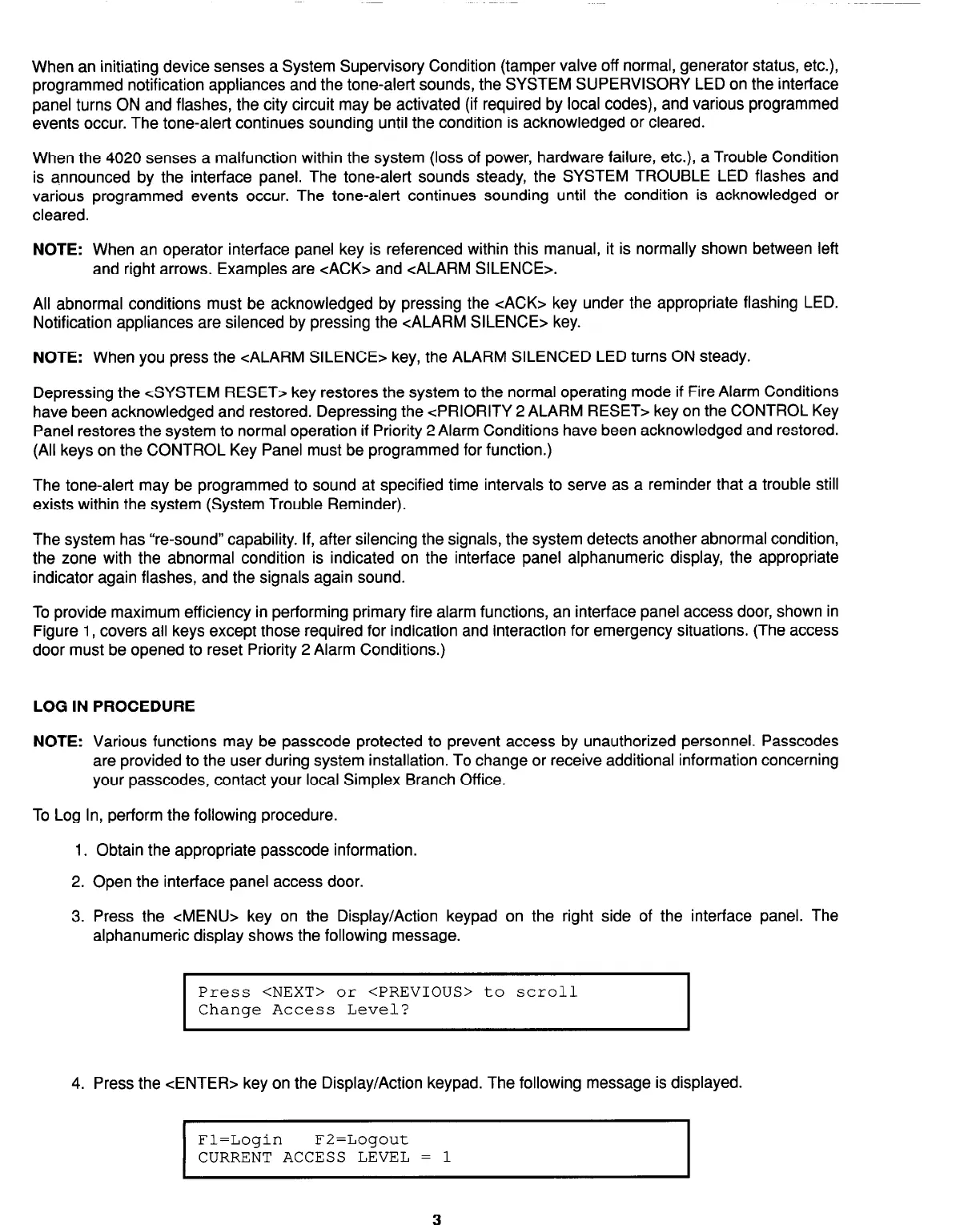
4. Press the <ENTER> key on the Display/Action keypad. The following message is displayed.
I
Fl=Login F2=Logout
CURRENT ACCESS LEVEL = 1
3
Technical Manuals Online! - http://www.tech-man.com