SECTION 1
SYSTEM OVERVIEW
INTRODUCTION
The Simplex 4020 is a microprocessor-based Fire Alarm System.
It is UL-listed, power-limited, electrically-
supervised, and protected against loss of primary AC power and brown-out conditions.
The standard 4020 can control up to 127 MAPNET II@ points. Depending on options, the 4020 can control a
maximum of 254 addressable points. Since all points in a system may not be addressable, the 4020 also offers up
to 20 hardwired points (with 4 points standard) that can be used to interface with detector zones, bell or horn circuits,
and auxiliary relay control. Each hardwired point is individually configurable as either a monitor point, a signal circuit,
or as an auxiliary relay output, with up to 8 different points on a single card.
The 4020 offers a variety of ways to provide remote annunciation. It can communicate with the LCD annunciator,
the SCWRCU, or the graphic SCWRCU. The RS-232 interface can be used to output to a printer or CRT.
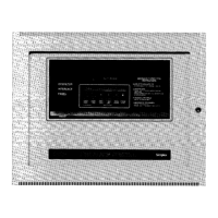
An alphanumeric display on the 4020 Operator Interface Panel (Figure 1) indicates the condition of the system. The
alphanumeric display shows various prompts and labels which guide the user through a sequenced operation for
each abnormal condition. Audible and visual indications are provided to indicate abnormal conditions when they
exist within the system.
The 4020 capacities are as follows:
l
Up to two MAPNET II@ channels with up to 127 addressable devices each for a total of 254 addressable
devices
l
Up to 20 hardwired points, configurable as monitor, signal, or auxiliary relay points
l
An RS-232 interface
l
Up to 31 remote annunciator locations, which can accommodate SCWRCU, graphic SCU/RCU, and LCD
annunciators
l
An 8-Amp switching power supply, with a battery charger capable of charging batteries with up to 50 Ah
capacity.
The default hardware for a 4020 includes a master controller with a display, master trouble points, city circuit, and
tone-alert. The standard slave module uses three card addresses. “Card (address) 1 W functions like an 8-point multi-
function I/O card, but only the first 4 points are available. “Card 2” is the power supply card. “Card 3” is the built-in
MAPNET@ channel.
The following optional hardware is allowed:
l
An additional MAPNET II@ card
l
Two eight-point multifunctional I/O cards
l
An RS-232 interface card configured with two isolated ports, with the ability for one port to be dedicated to
communications with a 2120 Multiplex System.
l
Serial annunciators including the LCD display, the SCWRCU, or the graphic SCWRCU
l
4120 Network Interface
l
25.5 Volt Limiter Module for Agent Release.
NOTE: This document covers operating procedures for a typical 4020 system. Applications will vary due to optional
hardware installed, custom programming, and local code requirements.
Technical Manuals Online! - http://www.tech-man.com

 Loading...


