SECTION 2
ALARM CONDITIONS
INTRODUCTION
CAUTION
FOLLOW LOCAL OPERATING PROCEDURES WHEN INVESTIGATING ALARM CONDITIONS.
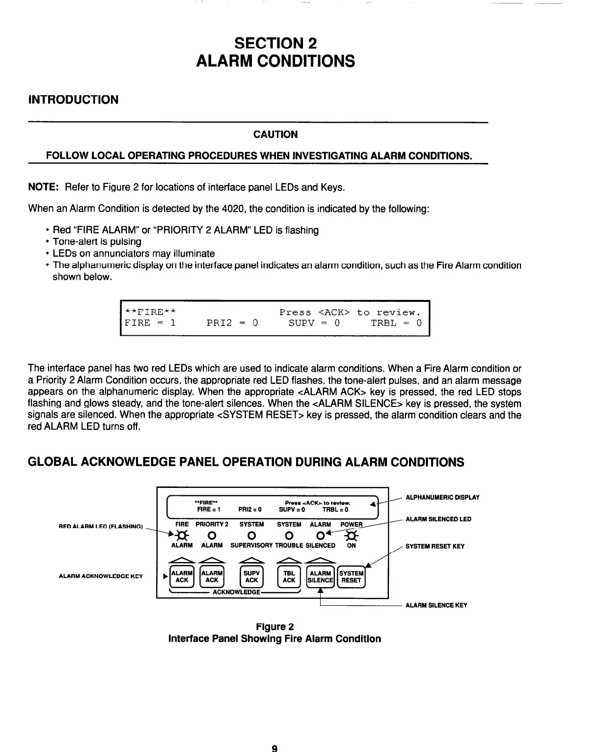
NOTE: Refer to Figure 2 for locations of interface panel LEDs and Keys.
When an Alarm Condition is detected by the 4020, the condition is indicated by the following:
l
Red “FIRE ALARM” or “PRIORITY 2 ALARM” LED is flashing
l
Tone-alert is pulsing
l
LEDs on annunciators may illuminate
l
The alphanumeric display on the interface panel indicates an alarm condition, such as the Fire Alarm condition
shown below.
I
**FIRE**
Press <ACK> to review.
FIRE = 1 PR12 = 0
SUPV = 0
TRBL = 0
I
The interface panel has two red LEDs which are used to indicate alarm conditions. When a Fire Alarm condition or
a Priority 2 Alarm Condition occurs, the appropriate red LED flashes, the tone-alert pulses, and an alarm message
appears on the alphanumeric display. When the appropriate <ALARM ACK> key is pressed, the red LED stops
flashing and glows steady, and the tone-alert silences. When the <ALARM SILENCE> key is pressed, the system
signals are silenced. When the appropriate <SYSTEM RESET> key is pressed, the alarm condition clears and the
red ALARM LED turns off.
GLOBAL ACKNOWLEDGE PANEL OPERATION DURING ALARM CONDITIONS
RED ALARM LED (FLASHING)
ALARM ACKNOWLEDGE KEY
I
‘*FIRE** Press <ACb to review.
FIRE z 1 PRl2 I 0 SUPV : 0
TRBL I 0
I
J
FlRE PRIORITY 2
--% 0
ALARM ALARM SUPERVISORY TROUBLE SILENCED
-ON-
/ ALPHANUMERIC DISPLAY
/ ALARM SILENCED LED
, SYSTEM RESET KEY
I ALARM SILENCE KEY
Figure 2
Interface Panel Showing Fire Alarm Condition
Technical Manuals Online! - http://www.tech-man.com