F
Jumpers
JW5 = Used to configure City Circuit connections. Jumper the following:
l
For Local Energy Box: JW5-2, -5, -7, -9, -12, -13
l
For Reverse Polarity: JW5-1, -3, -7, -8, -12
l
For Shunt Trip: JW5-1, -5, -13
l
For Radio Master: JW5-4, -6, -13
l
For Form C Contacts: JW5-13
l
For no connection: JW5-13.
NOTE: Hardware and software City Circuit configurations must agree.
l
See the Programmer’s Report for software-configured City Circuit connections.
l
Form “C” connection. The positive (+) terminal is the center (COMMON) strap of the relay.
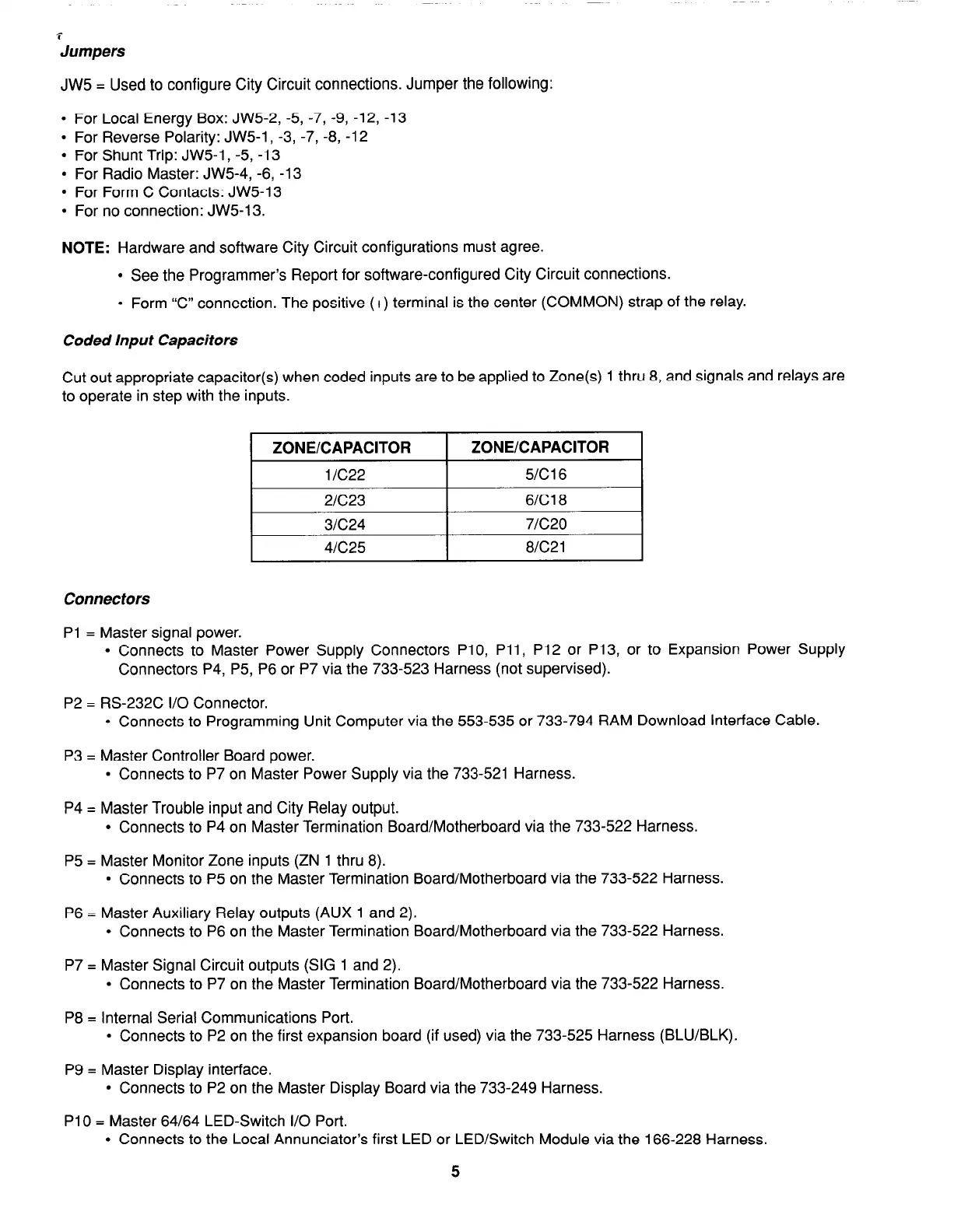
Coded Input Capacitors
Cut out appropriate capacitor(s) when coded inputs are to be applied to Zone(s) 1 thru 8, and signals and relays are
to operate in step with the inputs.
1 ZONE/CAPACITOR 1 Zt
3NE/CAPACITOR
I
1 IC22
I
5lC16
I
2/C23
I
6/C18
3/C24
7/C20
4lC25 8lC21
Connectors
PI = Master signal power.
l
Connects to Master Power Supply Connectors PlO, Pll, P12 or P13, or to Expansion Power Supply
Connectors P4, P5, P6 or P7 via the 733-523 Harness (not supervised).
P2 = RS-232C I/O Connector.
l
Connects to Programming Unit Computer via the 553-535 or 733-794 RAM Download Interface Cable.
P3 = Master Controller Board power.
l
Connects to P7 on Master Power Supply via the 733-521 Harness.
P4 = Master Trouble input and City Relay output.
l
Connects to P4 on Master Termination Board/Motherboard via the 733-522 Harness.
P5 = Master Monitor Zone inputs (ZN 1 thru 8).
l
Connects to P5 on the Master Termination Board/Motherboard via the 733-522 Harness.
P6 = Master Auxiliary Relay outputs (AUX 1 and 2).
l
Connects to P6 on the Master Termination Board/Motherboard via the 733-522 Harness.
P7 = Master Signal Circuit outputs (SIG 1 and 2).
l
Connects to P7 on the Master Termination Board/Motherboard via the 733-522 Harness.
P8 = Internal Serial Communications Port.
l
Connects to P2 on the first expansion board (if used) via the 733-525 Harness (BLU/BLK).
P9 = Master Display interface.
l
Connects to P2 on the Master Display Board via the 733-249 Harness.
PlO = Master 64/64 LED-Switch I/O Port.
l
Connects to the Local Annunciator’s first LED or LED/Switch Module via the 166-228 Harness.
5