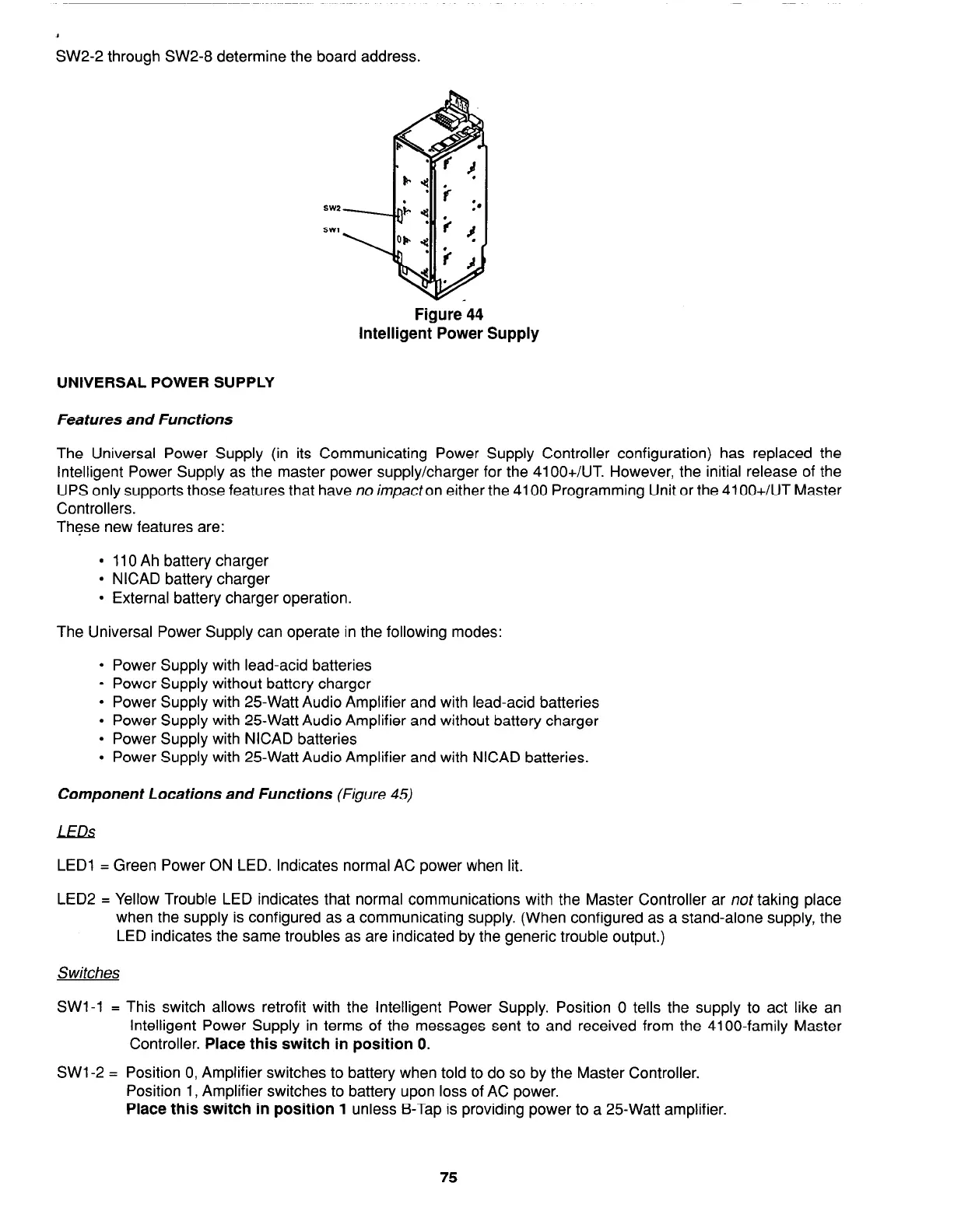
SW2-2 through SW2-8 determine the board address.
Figure 44
Intelligent Power Supply
UNIVERSAL POWER SUPPLY
Features and Functions
The Universal Power Supply (in its Communicating Power Supply Controller configuration) has replaced the
Intelligent Power Supply as the master power supply/charger for the 41 OO+/UT. However, the initial release of the
UPS only supports those features that have no impacton either the 4100 Programming Unit or the 41 OO+/UT Master
Controllers.
These new features are:
l
110 Ah battery charger
l
NICAD battery charger
l
External battery charger operation.
The Universal Power Supply can operate in the following modes:
l
Power Supply with lead-acid batteries
l
Power Supply without battery charger
l
Power Supply with 25Watt Audio Amplifier and with lead-acid batteries
l
Power Supply with 25Watt Audio Amplifier and without battery charger
l
Power Supply with NICAD batteries
l
Power Supply with 25Watt Audio Amplifier and with NICAD batteries.
Component Locations and Functions (Figure 45)
LEDs
LED1 = Green Power ON LED. Indicates normal AC power when lit.
LED2 = Yellow Trouble LED indicates that normal communications with the Master Controller ar not taking place
when the supply is configured as a communicating supply. (When configured as a stand-alone supply, the
LED indicates the same troubles as are indicated by the generic trouble output.)
Switches
SWl-1 = This switch allows retrofit with the Intelligent Power Supply. Position 0 tells the supply to act like an
Intelligent Power Supply in terms of the messages sent to and received from the 4100-family Master
Controller.
Place this switch in position 0.
SW1 -2 = Position 0, Amplifier switches to battery when told to do so by the Master Controller.
Position 1, Amplifier switches to battery upon loss of AC power.
Place this switch in position 1
unless B-Tap is providing power to a 25Watt amplifier.
75