Terminal Blocks
Terminate field wiring in accordance with the appropriate 4100 Field Wiring Diagram (841-731).
l
TBl = Terminates communications (from the RAI Card) and 24VDC power.
l
TB2 = Terminates piezo drive input (from LED/Switch Controller or Graphic I/O Card) and remote microphone
output (to TBl on Audio Controller).
REMOTE INTERFACE CARD II (565233)
NOTE:
This board is referred to as a “RIC II Card” (Remote [Serial] Interface Card, second version) elsewhere in
this publication, as well as the 4100 Fire Alarm parts List (FA4-81-218).
Features
l
Provides 8 volts for slave cards.
l
The RIC II supports Style 7 wiring.
l
The RIC II provides connections for 4100 serial communication devices, remote microphone, as well as a piezo
input for use as a local audible trouble signal.
l
Compatible with the Remote Unit Interface (RUI) part no. 565-217.
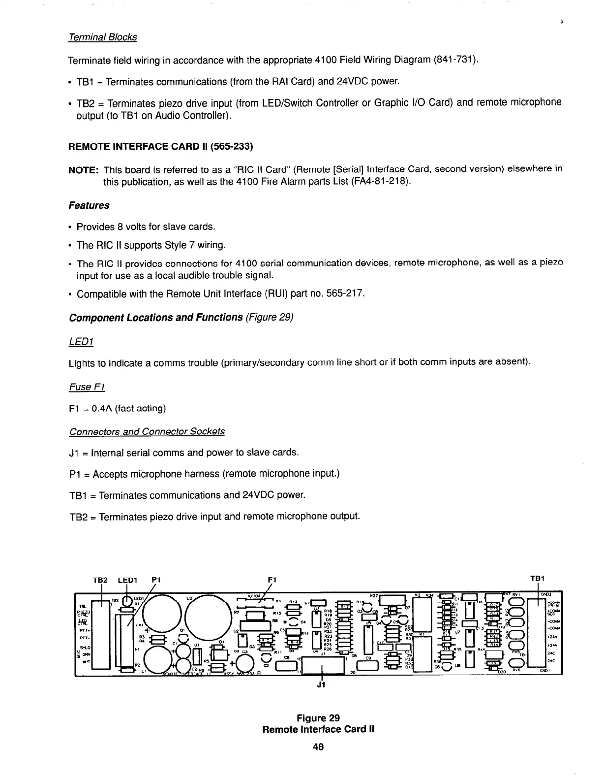
Component Locations and Functions (Figure 29)
LED1
Lights to indicate a comms trouble (primary/secondary comm line short or if both comm inputs are absent).
Fuse Fl
Fl = 0.4A (fast acting)
Connectors and Connector Sockets
Jl = Internal serial comms and power to slave cards.
Pl = Accepts microphone harness (remote microphone input.)
TBl = Terminates communications and 24VDC power.
TB2 = Terminates piezo drive input and remote microphone output.
TB2 LED1 Pl
Fl
TBl
Figure 29
Remote Interface Card II
48