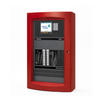
UT MASTER CONTROLLERS (565-148 and 565-333)
Two types of UT Master Controllers are available, each can be identified by the name and number it bears. Both
cards are a re-design of the 4100 Master Controller. The monitor zones, signal circuits, auxillary relays, feedback
and local annunciator points on the 4100 Master have been removed. Both cards contain the following
specifications:
Note:
The 565-333 supports the Priority 2 and Alarm Silenced LEDs.
l
System Code memory
l
CFIG Data memory
l
RAM Data memory
l
Watchdog circuit
l
5-Volt, (-)5-Volt, and 12-Volt regulators
l
Piezo drive plus piezo input
l
Internal communication driver and receiver (for 4100 slave communications)
l
Master display driver
l
Programmer interface
l
Battery backed RAM
l
City and Trouble controls
COMPONENT LOCATIONS AND FUNCTIONS
565-333 (FIGURE 3)
LED1
Lights if there is an on-board trouble, or if forced ON during tests.
IC Chips
U14 = Code PROM (lower system prom).
U16 = Code PROM (upper system prom).
Ull = CFIG Flash EPROM.
U6, U7, U8, UlO = System RAM.
U26 = Microprocessor.
SW1
SW1 = Reset switch to microcontroller
Fl
Fast Acting 4/l OA
Jumpers
Note:
Refer to FSBs 372R and 392R for additional information.
Shunt Jumper P2:
l
Normal and download: Plug jumper 166-157 onto pins 1 and 2.
l
Download from a modem: Plug jumper 166-l 57 onto pins 2 and 3.
Shunt Jumper P3:
l
To enable RAM Battery Backup: Plug jumper 166-157 onto pins 1 and 2.
l
To disable RAM Battery Backup: Plug jumper 166-l 57 onto pins 2 and 3.
Shunt Jumper P5:
l
To enable Flash EPROM writes: Plug jumper 166-157 onto pins 1 and 2.
l
To disable Flash EPROM writes: Plug jumper 166-l 57 onto pins 2 and 3.
6

 Loading...


