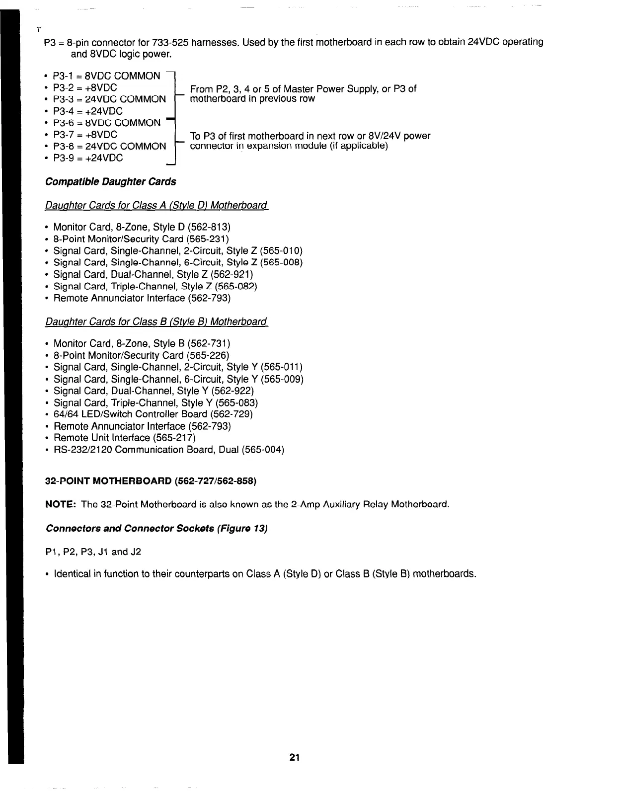
P3 = 8-pin connector for 733-525 harnesses. Used by the first motherboard in each row to obtain 24VDC operating
and 8VDC logic power.
l
P3-1 = 8VDC COMMON
l
P3-2 = +8VDC
l
P3-3 = 24VDC COMMON
l
P3-4 = +24VDC
l
P3-6 = 8VDC COMMON
l
P3-7 = +8VDC
l
P3-8 = 24VDC COMMON
l
P3-9 = +24VDC
i
Compatible Daughter Cards
From P2, 3, 4 or 5 of Master Power Supply, or P3 of
motherboard in previous row
To P3 of first motherboard in next row or 8V/24V power
connector in expansion module (if applicable)
Dauahter Cards for Class A (Stvle D) Motherboard
l
Monitor Card, 8-Zone, Style D (562-813)
l
8-Point Monitor/Security Card (565-231)
l
Signal Card, Single-Channel, 2-Circuit, Style Z (565-010)
l
Signal Card, Single-Channel, 6-Circuit, Style Z (565-008)
l
Signal Card, Dual-Channel, Style Z (562-921)
l
Signal Card, Triple-Channel, Style Z (565-082)
. Remote Annunciator Interface (562-793)
Dauahter Cards for Class B (Stvle BJ Motherboard
.
Monitor Card, 8-Zone, Style B (562-731)
.
8-Point Monitor/Security Card (565-226)
.
Signal Card, Single-Channel, 2-Circuit, Style Y (565-011)
.
Signal Card, Single-Channel, 6-Circuit, Style Y (565-009)
.
Signal Card, Dual-Channel, Style Y (562-922)
.
Signal Card, Triple-Channel, Style Y (565-083)
.
64/64 LED/Switch Controller Board (562-729)
.
Remote Annunciator Interface (562-793)
.
Remote Unit Interface (565-217)
.
RS-232/2120 Communication Board, Dual (565-004)
32-POINT MOTHERBOARD (562-727/562-858)
NOTE:
The 32-Point Motherboard is also known as the 2-Amp Auxiliary Relay Motherboard.
Connectors and Connector Sockets (Figure 13)
Pl, P2, P3, Jl and J2
l
Identical in function to their counterparts on Class A (Style D) or Class B (Style B) motherboards.
21