Features and Functions
Constantly monitors normally open alarm initiating device circuits (including 2-wire smoke detectors) for opens and
alarms.
Communicates with the Master Controller Board via Connector Pl on its motherboard.
Component Locations and Functions (Figure 16)
LED1
Lights when there is a trouble associated with the board.
Masked chip 246-399 contains the card’s program
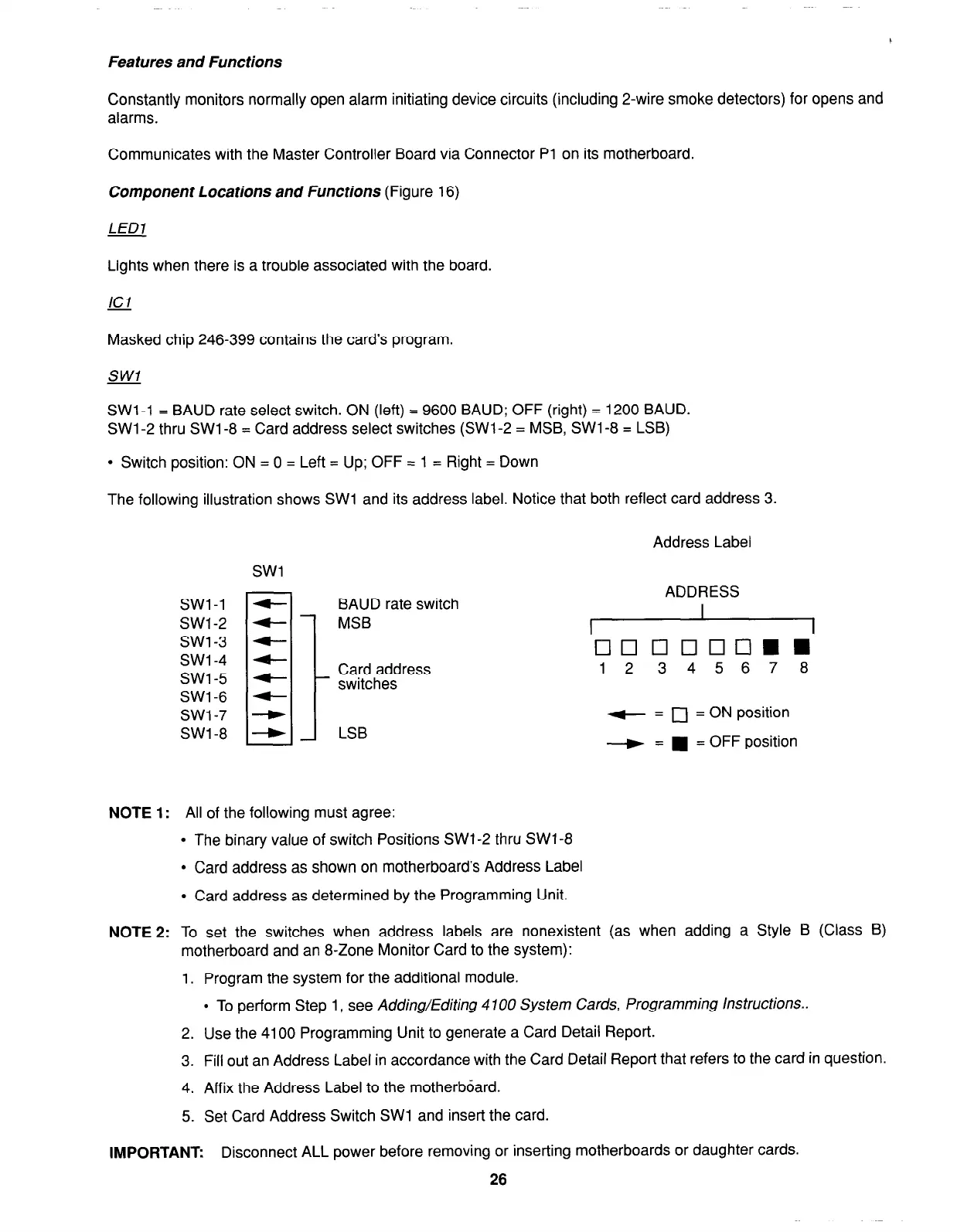
SW1 -1 = BAUD rate select switch. ON (left) = 9600 BAUD; OFF (right) = 1200 BAUD.
SW1 -2 thru SW1 -8 = Card address select switches (SWl-2 = MSB, SW1 -8 = LSB)
l
Switch position: ON = 0 = Left = Up; OFF = 1 = Right = Down
The following illustration shows SW1 and its address label. Notice that both reflect card address 3.
Address Label
SW1
ADDRESS
BAUD rate switch
MSB
I
I
1
cl0000ElmH
Card address
1 2
345678
switches
LSB
+ = 0 = ON position
-+ =
n
= OFF position
NOTE 1:
All of the following must agree:
l
The binary value of switch Positions SWl-2 thru SWl-8
l
Card address as shown on motherboard’s Address Label
l
Card address as determined by the Programming Unit.
NOTE
2: To set the switches when address labels are nonexistent (as when adding a Style B (Class B)
motherboard and an 8-Zone Monitor Card to the system):
1. Program the system for the additional module.
l
To perform Step 1, see Adding/Editing 4700 System Cards, Programming Instructions..
2. Use the 4100 Programming Unit to generate a Card Detail Report.
3. Fill out an Address Label in accordance with the Card Detail Report that refers to the card in question.
4. Affix the Address Label to the motherboard.
5. Set Card Address Switch SW1 and insert the card.
IMPORTANT:
Disconnect ALL power before removing or inserting motherboards or daughter cards.
26