NOTE:
The following jumpers are zero-ohm resistors.
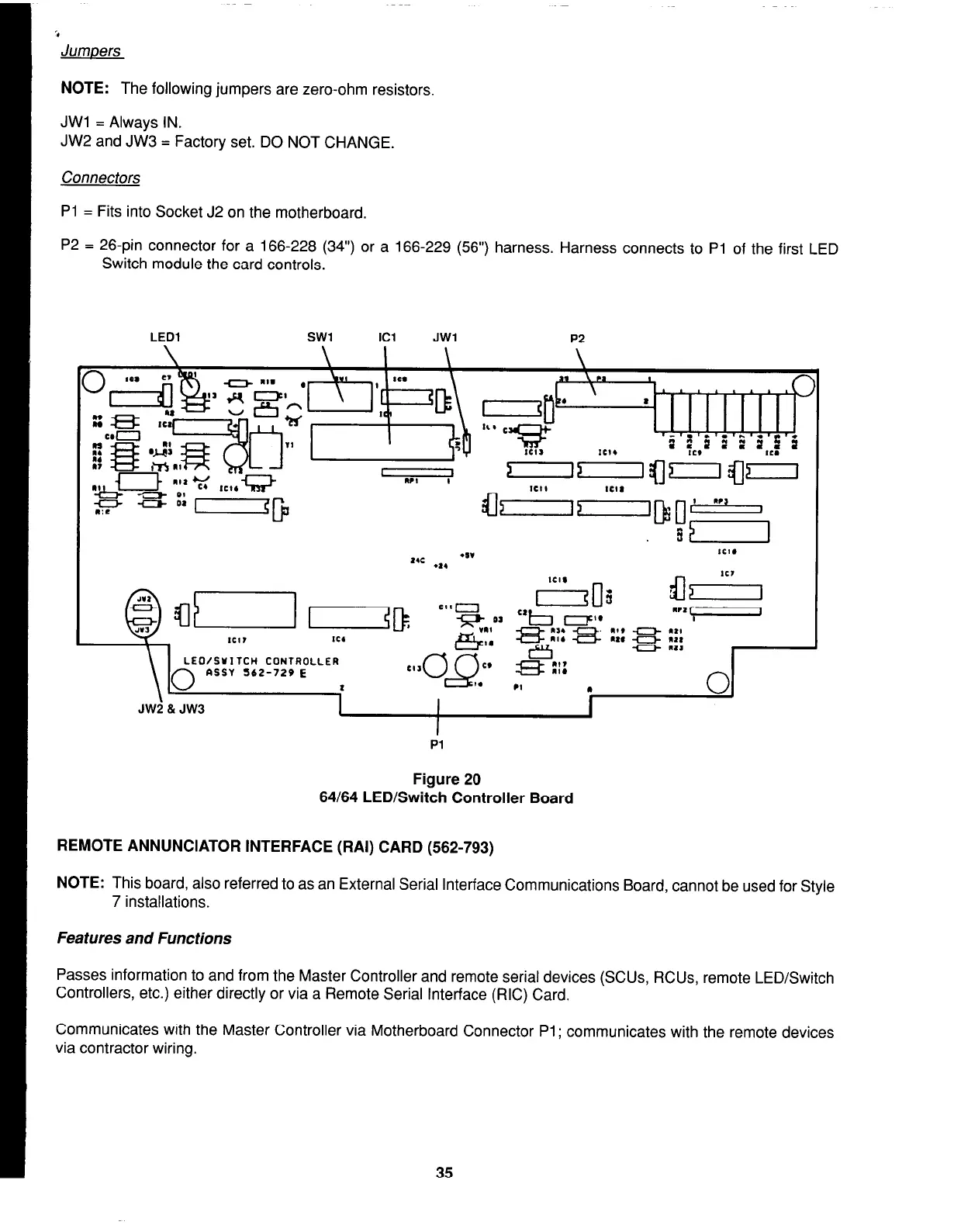
JWl = Always IN.
JW2 and JW3 = Factory set. DO NOT CHANGE.
Connectors
Pl = Fits into Socket J2 on the motherboard.
P2 = 26-pin connector for a 166-228 (34”) or a 166-229 (56”) harness. Harness connects to Pl of the first LED
Switch module the card controls.
LED1
SW1
Cl
JWl
P2
tc, I
u “‘1
,
LEO/SUITCH CONTROLLER
ASSY 562-729 E
JW2 81 JW3
1
I
I
Pl
Figure 20
64/64 LED/Switch Controller Board
REMOTE ANNUNCIATOR INTERFACE (RAI) CARD (562-793)
NOTE:
This board, also referred to as an External Serial Interface Communications Board, cannot be used for Style
7 installations.
Features and Functions
Passes information to and from the Master Controller and remote serial devices (SCUs, RCUs, remote LED/Switch
Controllers, etc.) either directly or via a Remote Serial Interface (RIC) Card.
Communicates with the Master Controller via Motherboard Connector Pl ; communicates with the remote devices
via contractor wiring.
35