STAND-ALONE BOARDS, CARDS. AND MODULES
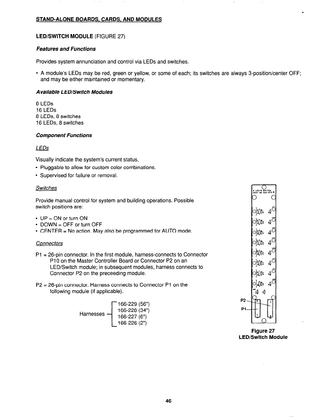
LED/SWITCH MODULE
(FIGURE 27)
Features and Functions
Provides system annunciation and control via LEDs and switches.
l
A module’s LEDs may be red, green or yellow, or some of each; its switches are always 3-position/center OFF;
and may be either maintained or momentary.
Available LED/Switch Modules
8 LEDs
16 LEDs
8 LEDs, 8 switches
16 LEDs, 8 switches
Component Functions
LEDs
Visually indicate the system’s current status.
l
Pluggable to allow for custom color combinations.
l
Supervised for failure or removal.
Switches
Provide manual control for system and building operations. Possible
switch positions are:
l
UP = ON or turn ON
l
DOWN = OFF or turn OFF
l
CENTER = No action. May also be programmed for AUTO mode.
Connectors
Pl = 26-pin connector. In the first module, harness-connects to Connector
Pi 0 on the Master Controller Board or Connector P2 on an
LED/Switch module; in subsequent modules, harness connects to
Connector P2 on the preceeding module.
P2 = 26-pin connector. Harness connects to Connector Pi on the
following module (if applicable).
i
166-229 (56”)
Harnesses
166-228 (34”)
166-227 (6”)
166-226 (2”)
46