r‘
Shunt Jumper P7:
. To operate with 565-331 (except Rev. Bl) Master Display (5-Volt LCD): Plug jumper 166-l 57 onto pins 1 and 2.
l
To operate with 565-l 73 and 565-331 (Rev. Bl) Master Displays (12-Volt LCD): Plug jumper 166-l 57 onto pins 2
and 3.
Connectors
Pl = Programmer Port.
l
This port is an RS232 output. It has internal serial communications. This port is used to download the CFIG
software.
P4 = Master Controller Board Edge Card Connect.
l
Connects to a 565-l 61 motherboard for power and comm connections, plus two external inputs.
P6 = Master Display Port.
l
Connects to the master display board (optional) and drives the display board’s LCD, LEDs, and keypad.
P8 = Not Used.
U6 U7 U8 UlO Ull u14
U16
LED1
P7 P6
-U26
-P8
Pl-
P2-
/
Fl
P3
I
I
I
I
P4 P5
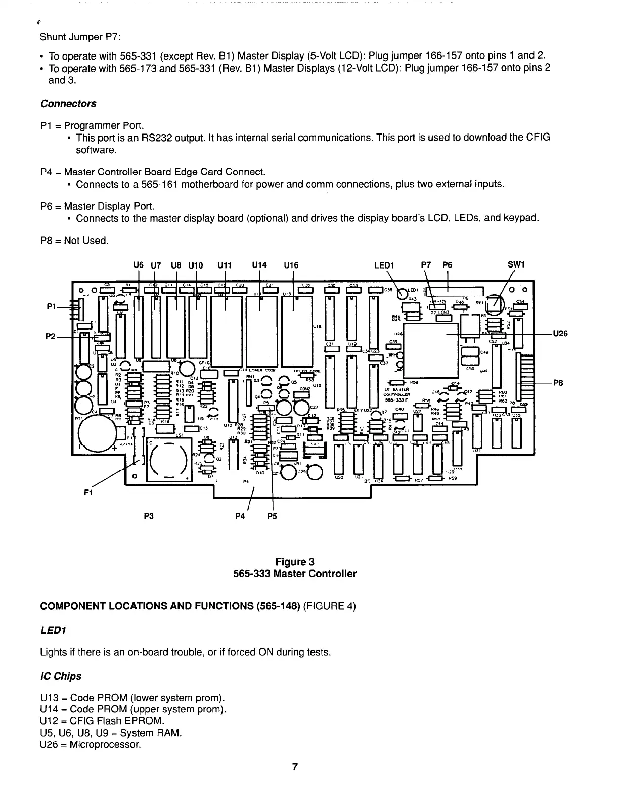
Figure 3
565-333 Master Controller
COMPONENT LOCATIONS AND FUNCTIONS (565-148)
(FIGURE 4)
LED1
Lights if there is an on-board trouble, or if forced ON during tests.
IC Chips
U13 = Code PROM (lower system prom).
U14 = Code PROM (upper system prom).
U12 = CFIG Flash EPROM.
U5, U6, U8, U9 = System RAM.
U26 = Microprocessor.
7