EasyManuals Logo

Simplex 4100 Service Instructions

Simplex 4100
98 pages
To Next Page IconTo Next Page
To Previous Page IconTo Previous Page
Page #50 background imageLoading...
Page #50 background image
The 246-399 masked chip contains the cards program.
sw1
Identical in function to Switch SW1 in an 8-Zone Monitor Card.
Jumoefs
NOTE:
The following jumpers are zero-ohm resistors.
CARD
TYPE
JWl JW2 JW3
JW4
JW5
JW6 JW7
JW8
JW9 JWlO
JWll
2A
IN IN
IN
See note below
OUT
OUT OUT
OUT
10A
IN IN
IN
OUT OUT
OUT
OUT IN
IN IN
IN
NOTE:
The 562-760 card jumpers are IN if Connector P2 on card provides power for controlled points otherwise
OUT.
l
Jumper JW4 is for Relay Kl
l
Jumper JW5 is for Relay K2
l
Jumper JW6 is for Relay K3
l
Jumper JW7 is for Relay K4.
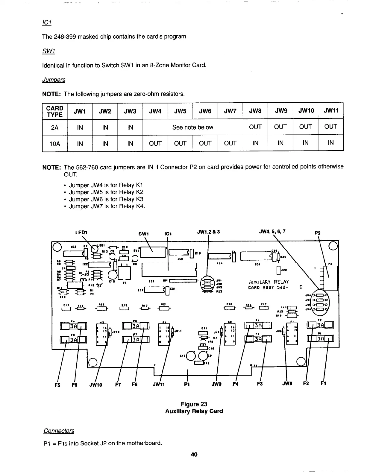
LED1
SW1
JW1,2&3
JW4,5,6,7
P2
F-S F-6
JiilO
fw%~uRV RELAY
CARD RSSY 562- D
I
JWll Pl
JW9 F4
F3
Figure 23
Auxiliary Relay Card
JW6 F2
Fl
Connectors
Pl
= Fits into Socket J2 on the motherboard.
40
firealarmresources.com

Table of Contents

Other manuals for Simplex 4100

Questions and Answers:

Question and Answer IconNeed help?

Do you have a question about the Simplex 4100 and is the answer not in the manual?

Simplex 4100 Specifications

General IconGeneral
TypeFire Alarm Control Panel
ManufacturerSimplex
Model4100
Network CapabilityYes
AddressableYes
Power Supply120/240 VAC, 50/60 Hz
DisplayLCD
Annunciator SupportYes
Battery BackupYes
Releasing CapabilityYes
Max DevicesDepends on configuration
Max Notification Appliance Circuits (NAC)Varies with configuration
Max Releasing CircuitsVaries with configuration
Max Remote AnnunciatorsVaries with configuration
Communication PortsMultiple
Operating Temperature32°F to 120°F (0°C to 49°C)
Humidity RangeUp to 93% RH, non-condensing
NAC Outputs4 (expandable)
NetworkingYes

Related product manuals