EasyManuals Logo

Simplex 4100 Service Instructions

Simplex 4100
98 pages
To Next Page IconTo Next Page
To Previous Page IconTo Previous Page
Page #52 background imageLoading...
Page #52 background image
Pluaaable Resistors
Input points (switches) require 378-253 (2K, l/2 W) resistors; output points (lamps) require 382-110 (20 Ohm, 1 W,
wire wound) resistors.
SW1 -1 = BAUD rate select switch.
l
ON (left) if card is within the panel.
l
ON (left) if card is remote from the panel and external communication is at 9600 BAUD.
l
OFF (right) if card is remote from the panel andexternal communication is at 1200 BAUD.
SW1 -2 thru SW1 ?8 = Card address select switches.
l
Identical in function to Switches SW1 -2 thru SW1 -8 in an 8-Zone Monitor Card.
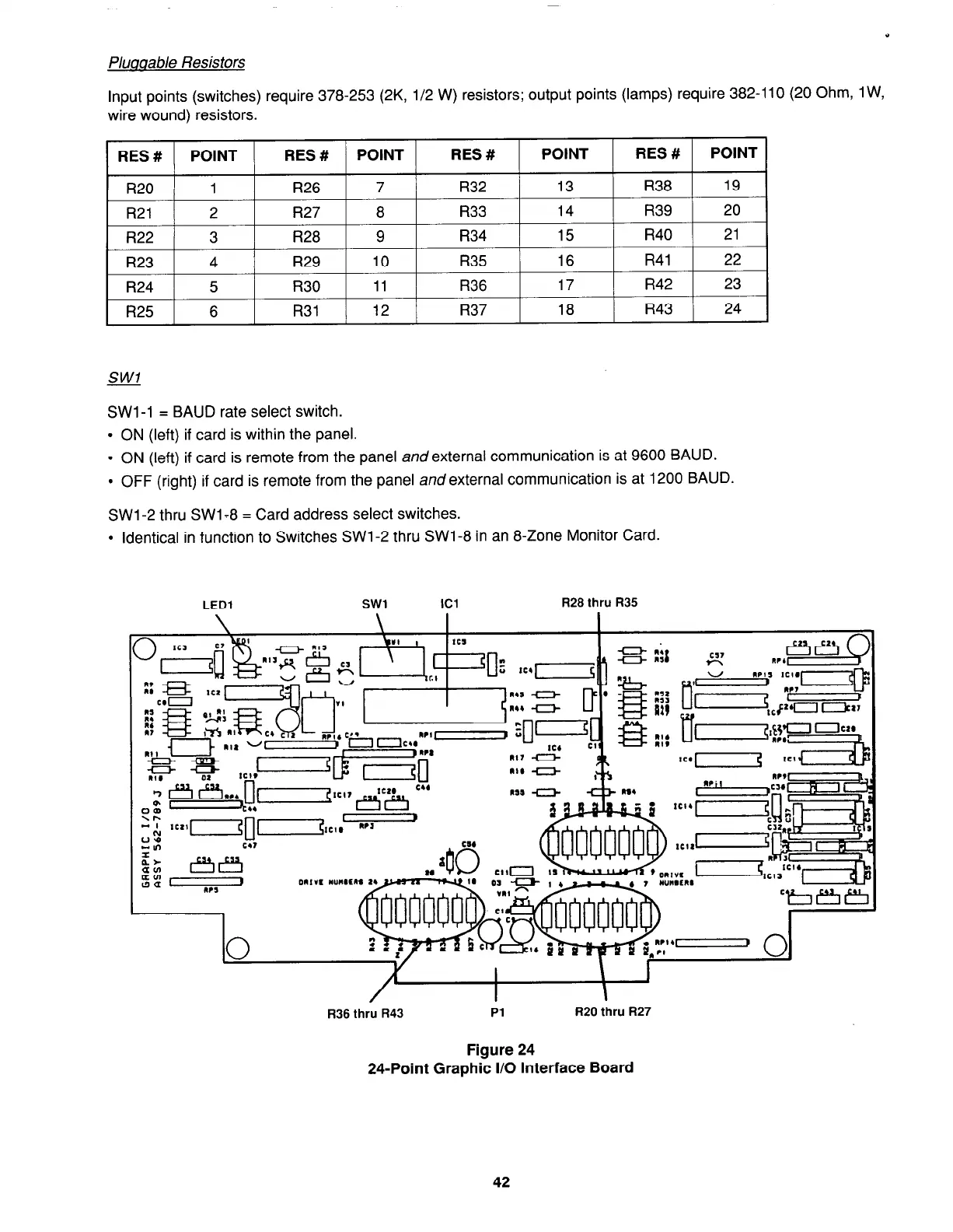
LED1
R28 thru R35
R36 thru R43
Pl
Figure 24
R20 thru R27
24-Point Graphic I/O Interface Board
42
firealarmresources.com

Table of Contents

Other manuals for Simplex 4100

Questions and Answers:

Question and Answer IconNeed help?

Do you have a question about the Simplex 4100 and is the answer not in the manual?

Simplex 4100 Specifications

General IconGeneral
TypeFire Alarm Control Panel
ManufacturerSimplex
Model4100
Network CapabilityYes
AddressableYes
Power Supply120/240 VAC, 50/60 Hz
DisplayLCD
Annunciator SupportYes
Battery BackupYes
Releasing CapabilityYes
Max DevicesDepends on configuration
Max Notification Appliance Circuits (NAC)Varies with configuration
Max Releasing CircuitsVaries with configuration
Max Remote AnnunciatorsVaries with configuration
Communication PortsMultiple
Operating Temperature32°F to 120°F (0°C to 49°C)
Humidity RangeUp to 93% RH, non-condensing
NAC Outputs4 (expandable)
NetworkingYes

Related product manuals